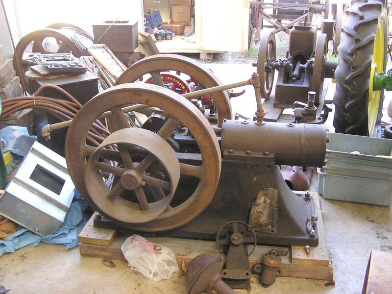
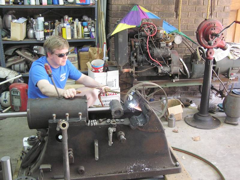
 This diamond in the rough was in the hands of a collector that had lost interest
in the project.
This diamond in the rough was in the hands of a collector that had lost interest
in the project. Click on the thumbnails for a full sized image. Close that image to return to this page.
This diamond in the rough was in the hands of a collector that had lost interest
in the project.
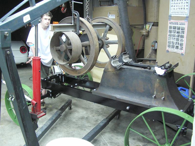
 Luckily most everything was there, although scattered around the shop.
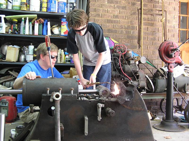
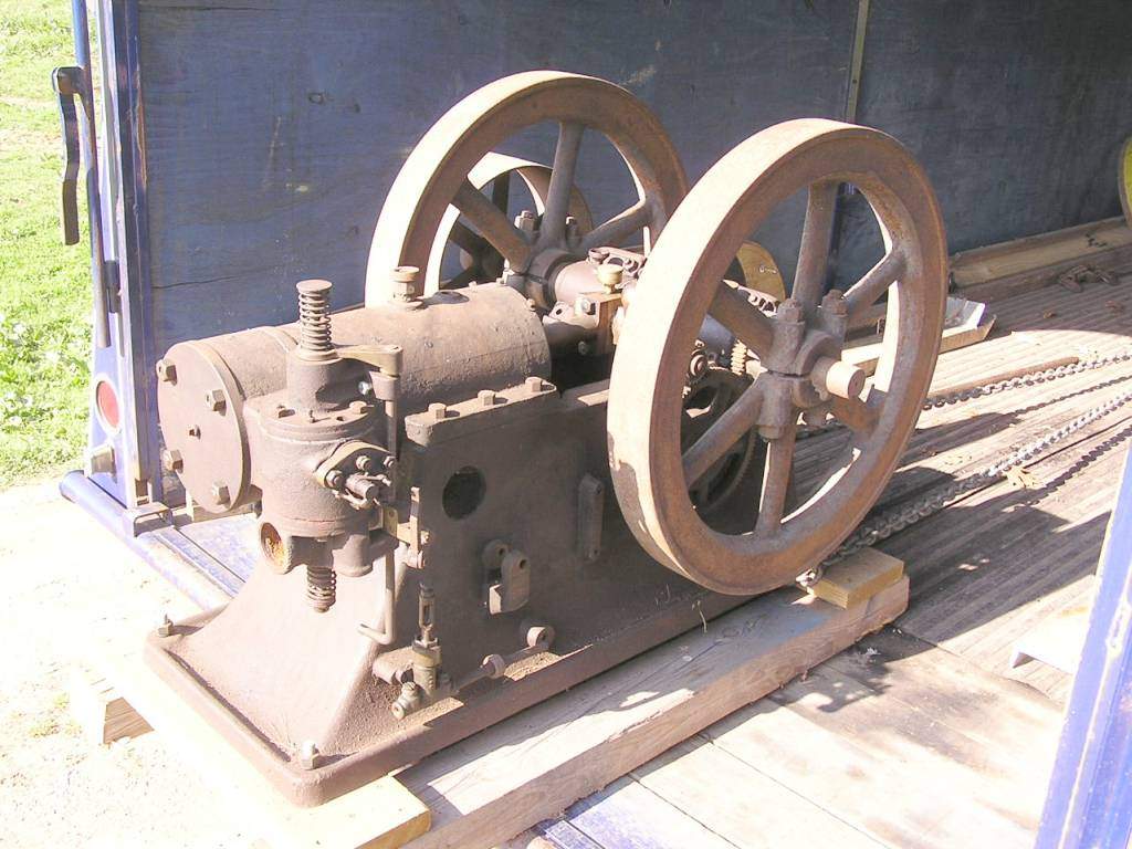 A little rigging and this beast was on the back of the trailer.
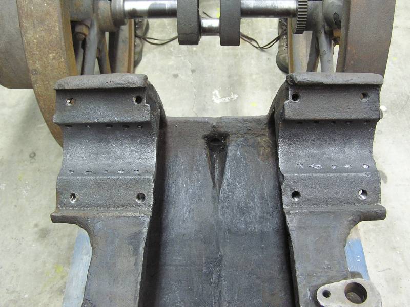
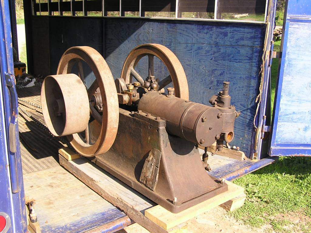 And a view from the other side. The wedge laying on the base is a wedge of
babbitt that goes under the water pump flange to account for the draft in the
base casting. Rather than cast the base on the water pump to match, they just
poured babbitt behind the water pump base to make it square.
And a view from the other side. The wedge laying on the base is a wedge of
babbitt that goes under the water pump flange to account for the draft in the
base casting. Rather than cast the base on the water pump to match, they just
poured babbitt behind the water pump base to make it square.
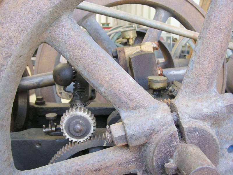 Here you can see the fiber gear on the 3 ball vertical flyball governor. Anyone
know why they used a fiber gear?
Here you can see the fiber gear on the 3 ball vertical flyball governor. Anyone
know why they used a fiber gear?
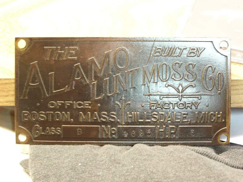 The tag is really in excellent shape. One small scratch just left of the word
"Built". It must have been mounted to the missing sheetmetal crankguard, as
there are no holes on the engine to mount the tag to.
The tag is really in excellent shape. One small scratch just left of the word
"Built". It must have been mounted to the missing sheetmetal crankguard, as
there are no holes on the engine to mount the tag to.
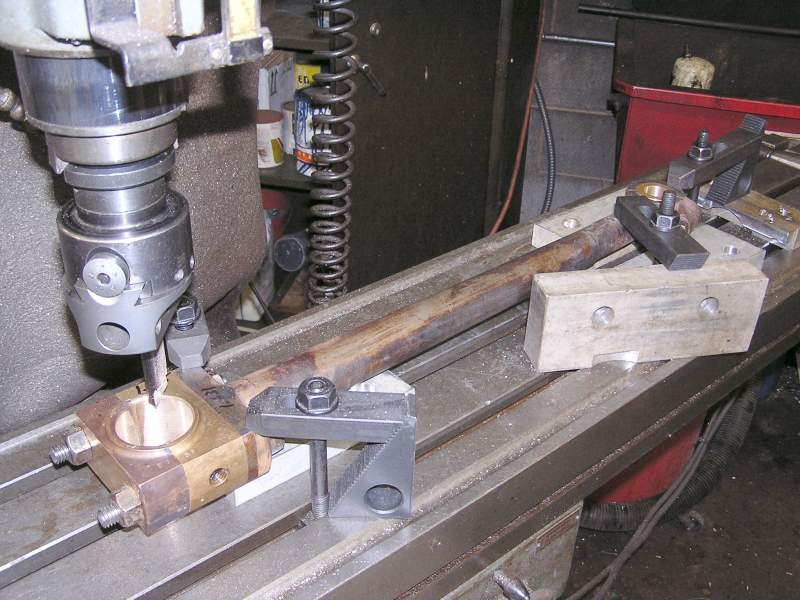
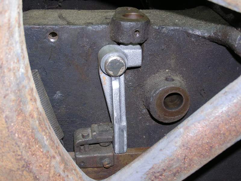 The first order of business was to make the one missing casting on the engine,
the latchout arm. With Edd Payne's help and some great photos and dimensions, a
pattern was made and shipped to
Rick Rowlands for casting. Here the casting has
the first machining step done on it, boring the pivot pin mount. The vertical flyball governor pushes down on the small horizontal tab
at the top, and when up to speed,
moves the long lower arm to the left, latching out the walking beam.
The first order of business was to make the one missing casting on the engine,
the latchout arm. With Edd Payne's help and some great photos and dimensions, a
pattern was made and shipped to
Rick Rowlands for casting. Here the casting has
the first machining step done on it, boring the pivot pin mount. The vertical flyball governor pushes down on the small horizontal tab
at the top, and when up to speed,
moves the long lower arm to the left, latching out the walking beam.
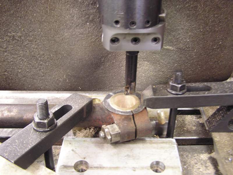
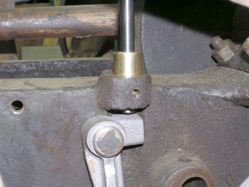 This step was to correctly locate where the governor pushrod would feed into the
latchout arm. The brass bushing was made to hold the centerpunch on the
centerline of the governor mount.
This step was to correctly locate where the governor pushrod would feed into the
latchout arm. The brass bushing was made to hold the centerpunch on the
centerline of the governor mount.
The finished latchout arm with the 3 ball vertical flyball governor in place.
 The connecting rod needed some first aide. Tommy Berry TIG brazed the brass
interlocks up so I could re-machine them so they are tight again (sorry no
pictures). Once machined and square again it was bolted to the connecting rod and set
on correct pins to account for the different width's of the bosses on each end
of the rod. Centerline of the bore was found and bored for a .003 clearance.
The connecting rod needed some first aide. Tommy Berry TIG brazed the brass
interlocks up so I could re-machine them so they are tight again (sorry no
pictures). Once machined and square again it was bolted to the connecting rod and set
on correct pins to account for the different width's of the bosses on each end
of the rod. Centerline of the bore was found and bored for a .003 clearance.
 In the same setup the wrist pin bore was done to assure both ends are parallel.
3/29/06 update:
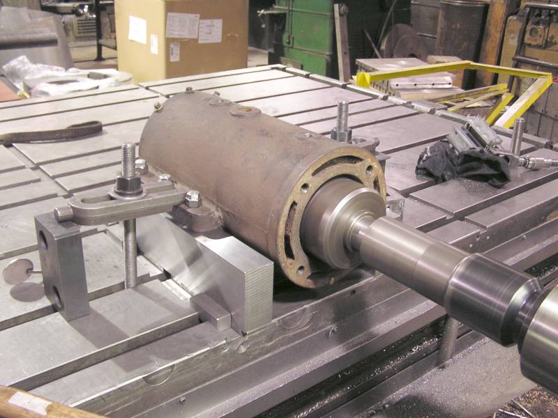
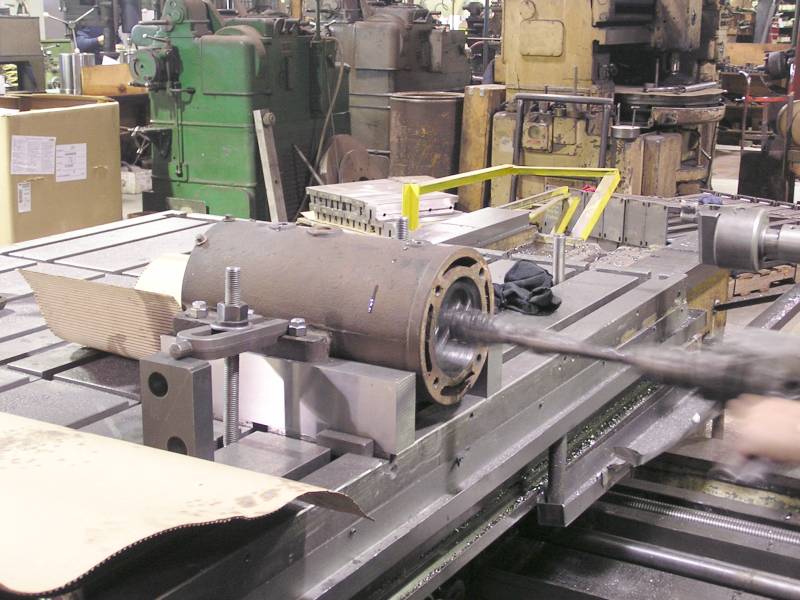
 Some measuring on the cylinder revealed what the naked eye already tells
one....that this bore needs some attention! The cylinder is being set up on a
Cincinnati horizontal boring mill.
Some measuring on the cylinder revealed what the naked eye already tells
one....that this bore needs some attention! The cylinder is being set up on a
Cincinnati horizontal boring mill.
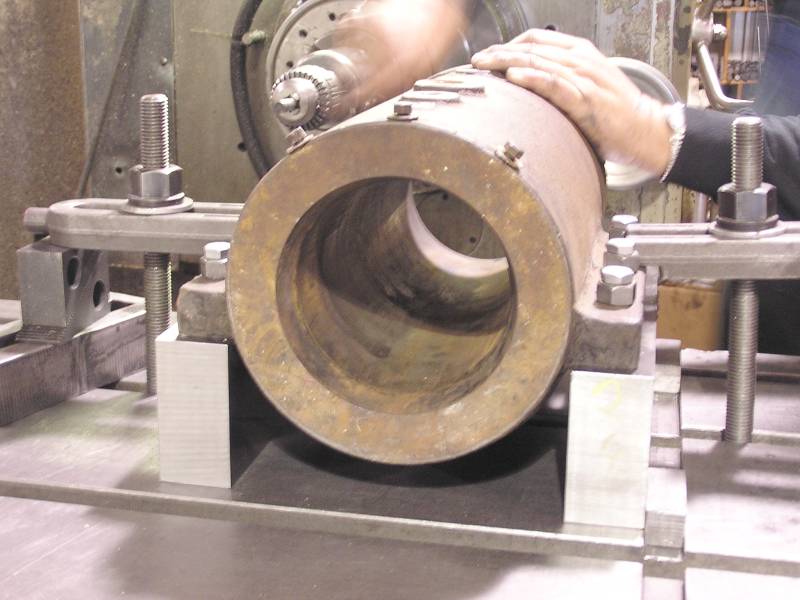
 A while back I made and ground a set of parallels 4 x 2 x 18 with some common
cylinder bolt patterns on them. Here you see the cylinder sitting on the
parallels and clamped to the mill table. Using the parallels makes locating on
the table and finding horizontal centerline a breeze. This proved to be a real
time saver. The large boring head is making the first pass thru the cylinder.
A while back I made and ground a set of parallels 4 x 2 x 18 with some common
cylinder bolt patterns on them. Here you see the cylinder sitting on the
parallels and clamped to the mill table. Using the parallels makes locating on
the table and finding horizontal centerline a breeze. This proved to be a real
time saver. The large boring head is making the first pass thru the cylinder.
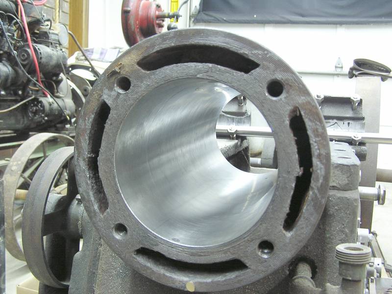
 The boring work has been done and checking with mics it is straight within .0015
to .002 in the 17" of cylinder length....pretty decent! Finally some honing to
get the bore nice and smooth and she's done. It was 4 hours from start to
finish.
The boring work has been done and checking with mics it is straight within .0015
to .002 in the 17" of cylinder length....pretty decent! Finally some honing to
get the bore nice and smooth and she's done. It was 4 hours from start to
finish.
 Here the cylinder is back at home sitting in place on the engine base.
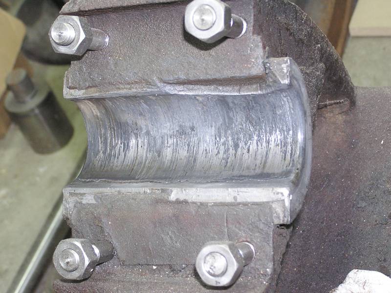 Now that the bore is straight the babbitt pouring fixture can be
located in the cylinder to repour these stuffed mains. This one got pretty hot
at some point.
Now that the bore is straight the babbitt pouring fixture can be
located in the cylinder to repour these stuffed mains. This one got pretty hot
at some point.
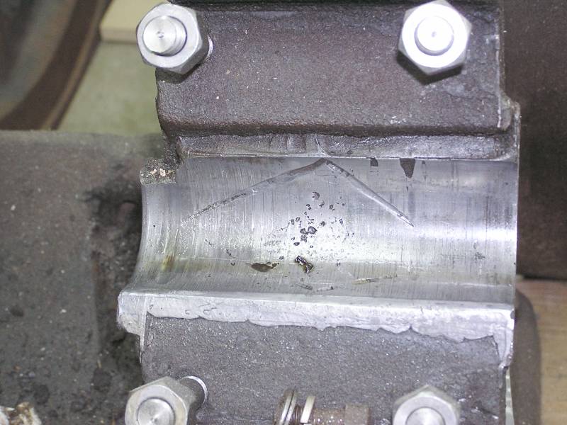 This side is decent, but still worn a little low.
 Missy took this picture as I was melting one of the babbitt bearings out.
 Devin took over the melting as this is something he really enjoys doing.
 Here the babbitt has been all melted out and everything is cleaned up with a
wire brush.
Here the babbitt has been all melted out and everything is cleaned up with a
wire brush.
More to come later.....
fast forwarding......
8/10/06 Assembly time.
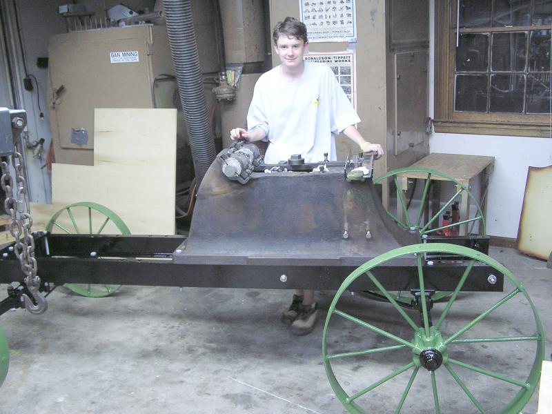 An engine cart was located, blasted, and painted. The green on the wheels
matches some of the original paint still on the engine. The base has been lifted
and placed on the cart.
An engine cart was located, blasted, and painted. The green on the wheels
matches some of the original paint still on the engine. The base has been lifted
and placed on the cart.
 The flywheels are being lifted to the right height and the cart & base will be
moved under them.
The flywheels are being lifted to the right height and the cart & base will be
moved under them.
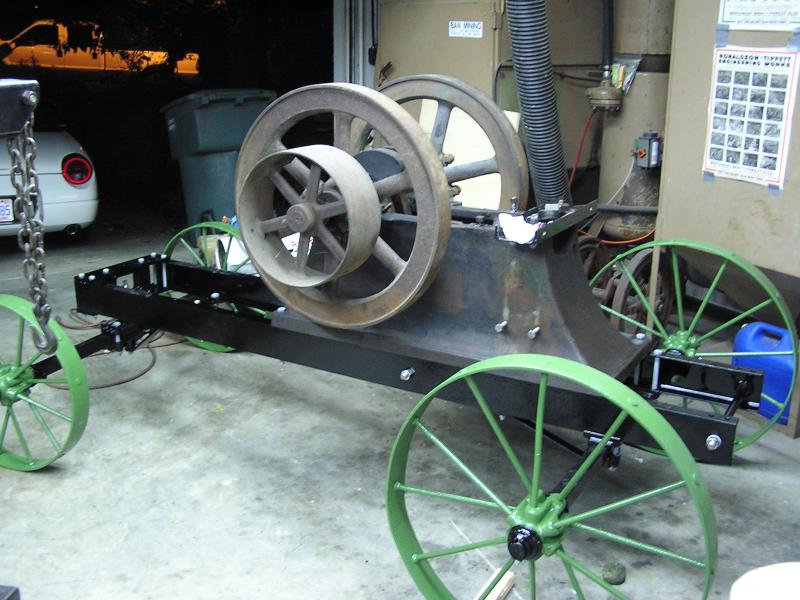 Whew! Flywheels are safely in place.
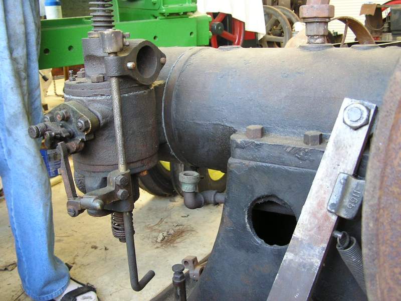
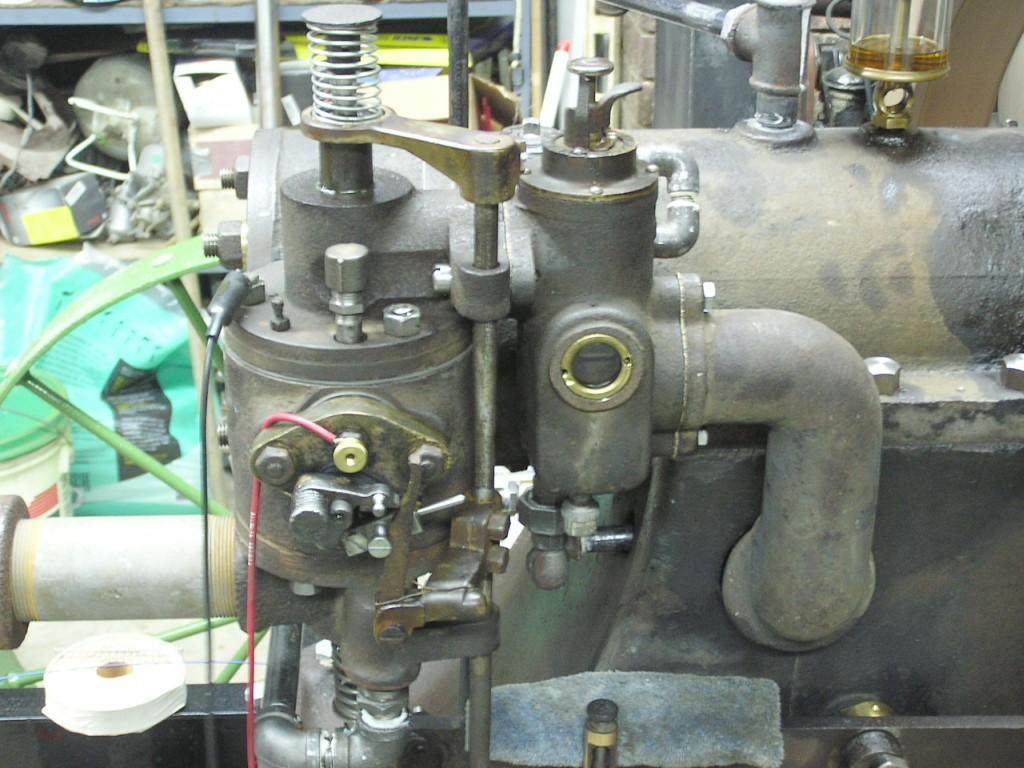 A couple of days of assembly later and a weeks worth of pipe fitting to the fuel
and cooling system and she's about ready to fire up. Here is a closeup of the
ignitor, valve chests, mixer, and intake horn.
A couple of days of assembly later and a weeks worth of pipe fitting to the fuel
and cooling system and she's about ready to fire up. Here is a closeup of the
ignitor, valve chests, mixer, and intake horn.
She's running!
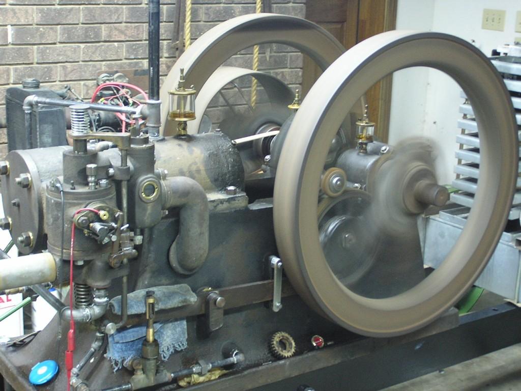 Front
operator's view.
Front
operator's view.
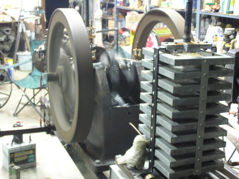 Cooling system uses a tray cooler.
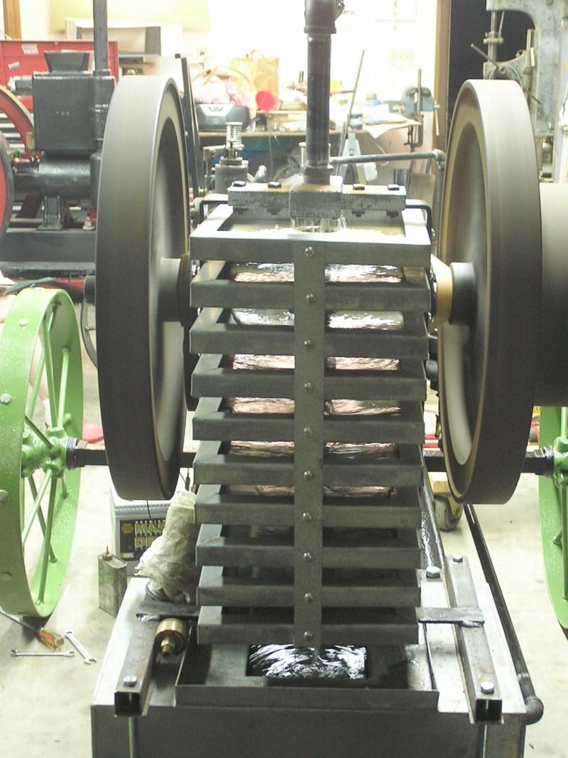 Here you can see the trays filled with water, cooling the water along the way.
The ignitor is still quite temperamental but maybe she'll be decent enough to make Baraboo or Portland.....
The links to the piston pattern making portion of this project are at:
http://www.oldengine.org/members/holland/images/AlamoPistonPattern/Thumbnails.html
And the link to the babbitt pouring portion are at:
http://www.oldengine.org/members/holland/images/AlamoBabbittPouring/Thumbnails.html
Hope you've enjoyed these photos....
Curt