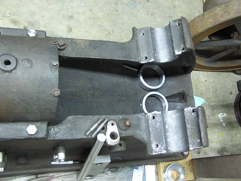
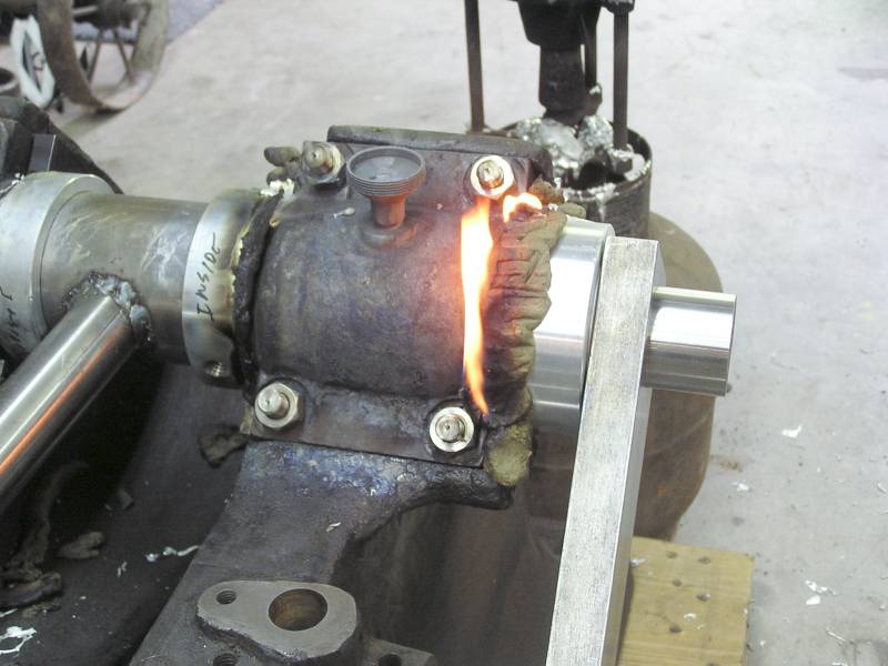
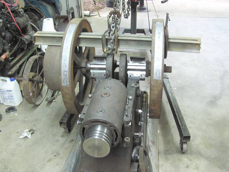
 The old bearings were melted out as they were worn low.
Click on the thumbnails for a full sized image. Close that image to return to this page.
The old bearings were melted out as they were worn low.
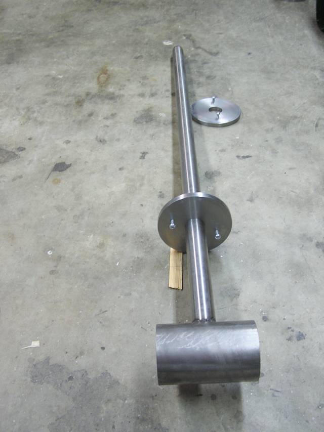 A precision tool was made to locate the bearings on center, both vertically and
horizontally. The discs are a thou clearance to the bore and will slip in each
end of the cylinder.
A precision tool was made to locate the bearings on center, both vertically and
horizontally. The discs are a thou clearance to the bore and will slip in each
end of the cylinder.
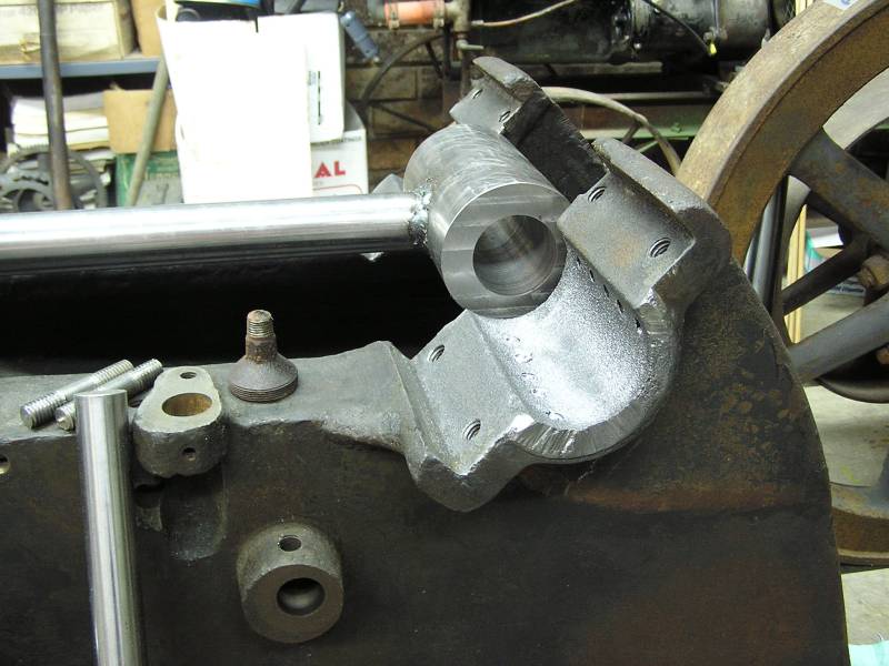
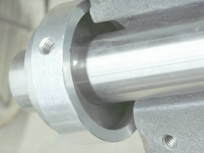
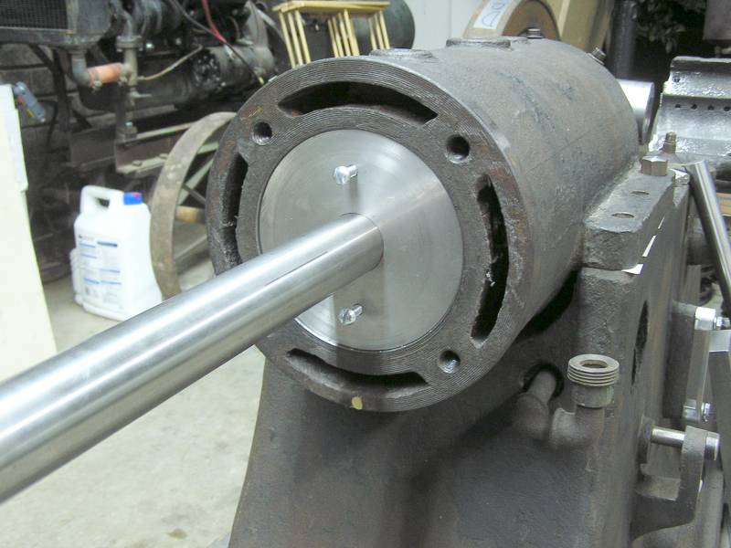 Here the centering fixture is in place in the bore. The small screws are just to
give you something to hold on to, to position the discs in the bore.
Here the centering fixture is in place in the bore. The small screws are just to
give you something to hold on to, to position the discs in the bore.
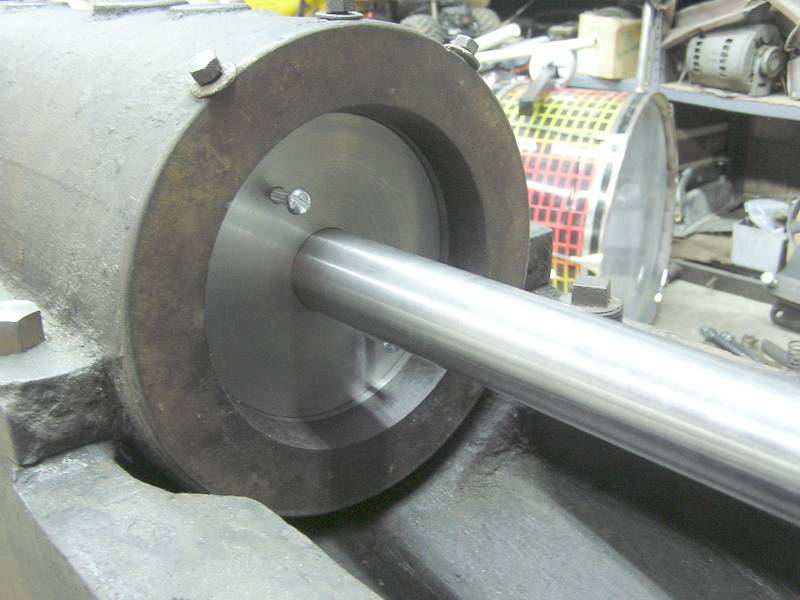 And a view from the other end.
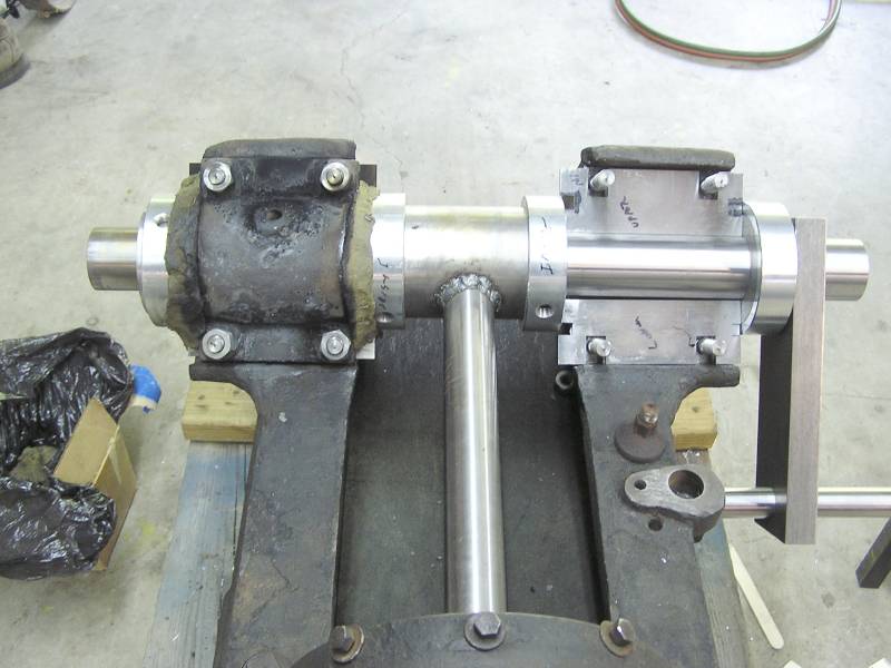
 Here you can see how the fixture will hold the dummy shaft that the babbitt will
be poured around.
Here you can see how the fixture will hold the dummy shaft that the babbitt will
be poured around.
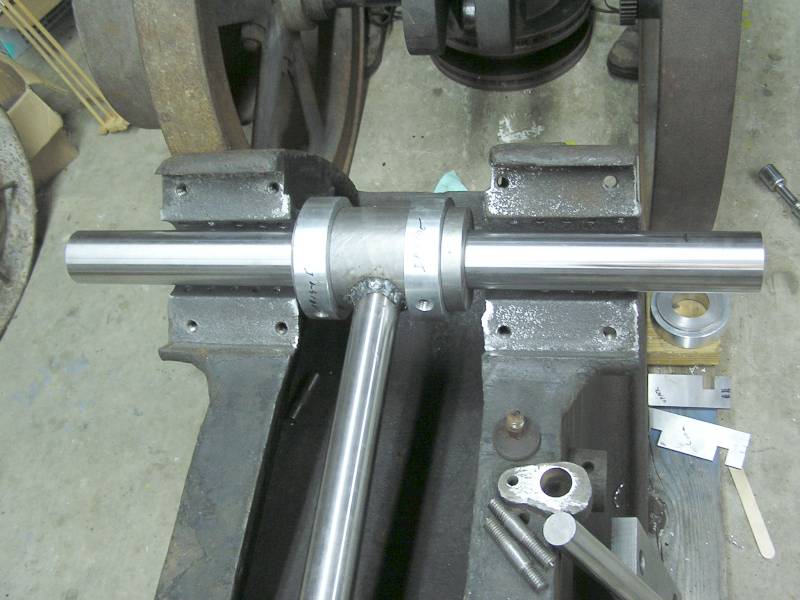 Dummy shaft in place.
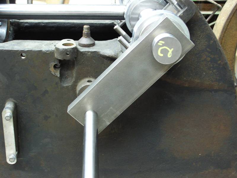 This bar accurately locates the dummy shaft the correct distance from the cam
gear. Actually I added .010 to the standard diametral spacing to account for
future wear in the bearings for years to come.
This bar accurately locates the dummy shaft the correct distance from the cam
gear. Actually I added .010 to the standard diametral spacing to account for
future wear in the bearings for years to come.
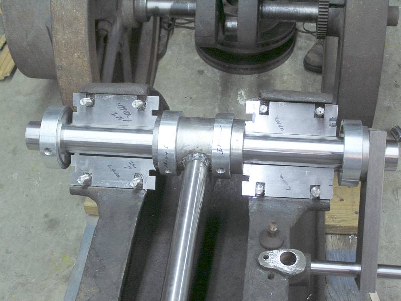
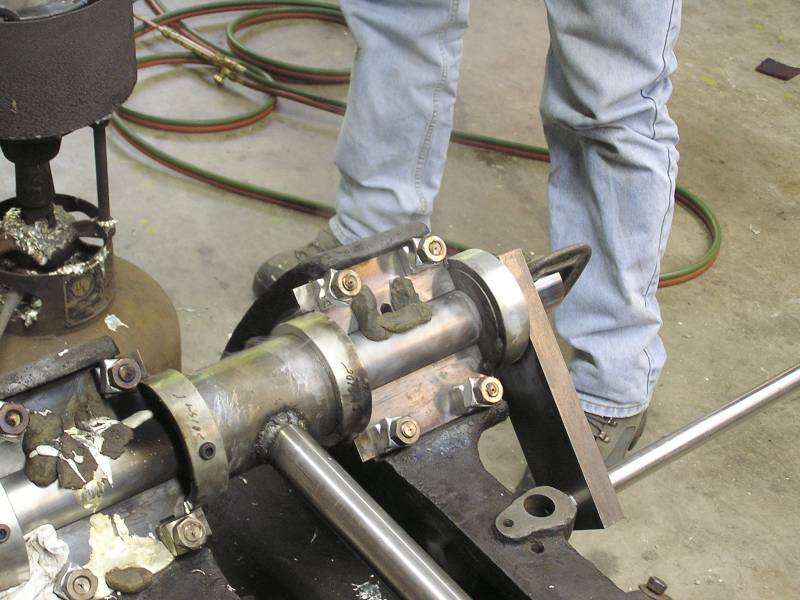
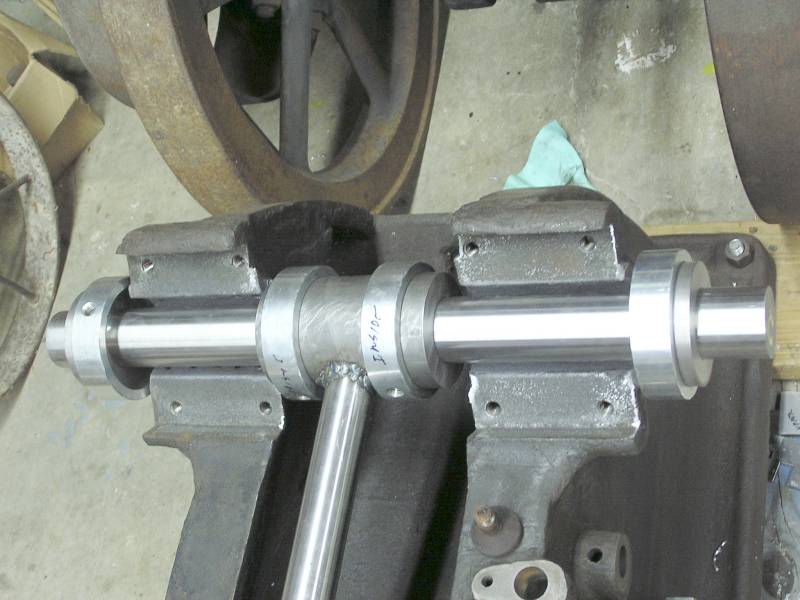 The end caps and collars have been added. The end caps (along with the spacer
shims) will determine the total bearing width. The sliding collars will be moved
up against the frame and will form the outside of the bearing that is outboard
of the saddle. These will be sealed with Babbitte Rite.
The end caps and collars have been added. The end caps (along with the spacer
shims) will determine the total bearing width. The sliding collars will be moved
up against the frame and will form the outside of the bearing that is outboard
of the saddle. These will be sealed with Babbitte Rite.
 Here is a close-up of how the end cap and collar will work.
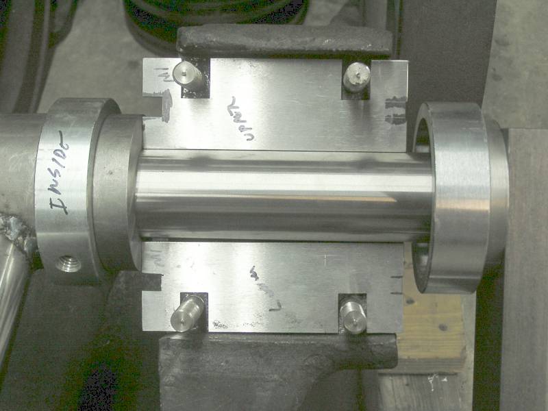
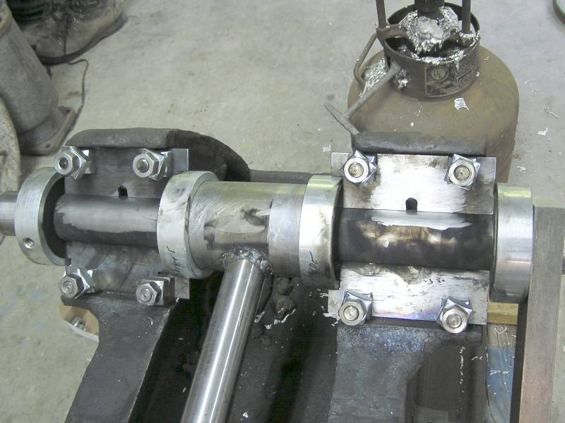
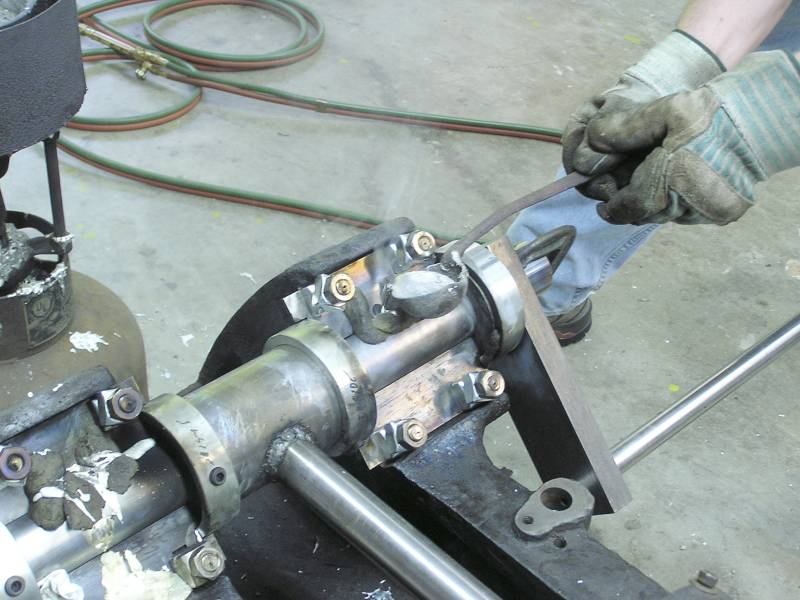
 Here the spacer shims have been added. They are the same width as the mains on
the crankshaft are wide. The notches on the end allow the sliding collars to
slide up tight to the frame saddles.
Here the spacer shims have been added. They are the same width as the mains on
the crankshaft are wide. The notches on the end allow the sliding collars to
slide up tight to the frame saddles.
 A close-up of the shims. It's pouring time!
The upper caps were poured first.
 Here the offside upper cap is being readied for pouring. The Babbitt Rite is in
place and preheating has begun. Last week on the list was a discussion of cooler
temperatures for the engine parts so I decided to try this. Using an IR gun the
cap was 230-250 ° F when the babbitt was poured in.
Here the offside upper cap is being readied for pouring. The Babbitt Rite is in
place and preheating has begun. Last week on the list was a discussion of cooler
temperatures for the engine parts so I decided to try this. Using an IR gun the
cap was 230-250 ° F when the babbitt was poured in.
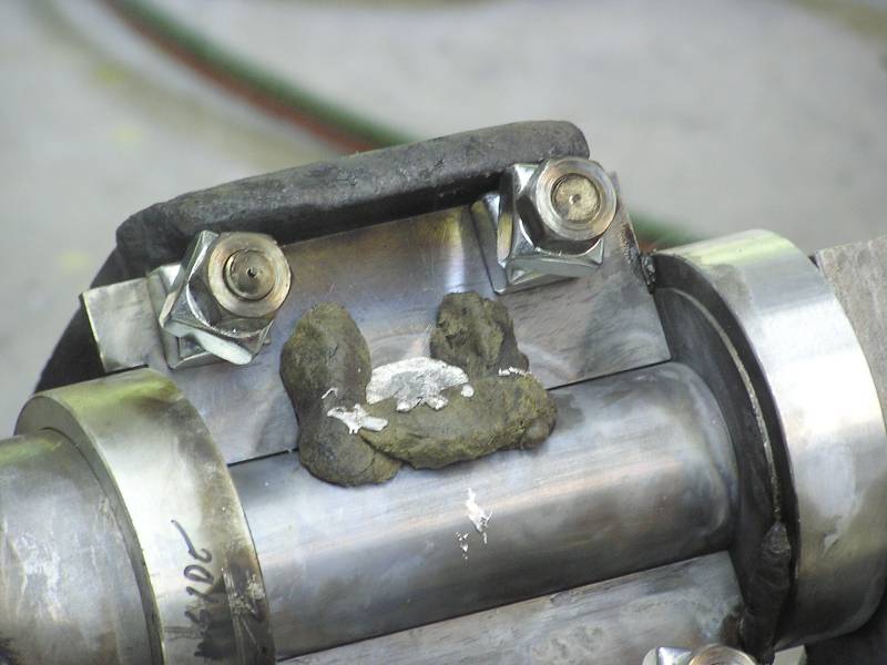
 Hmmm, this didn't work too well! The cooler temps might have worked had I used a
larger ladle, but it was all I had. These bearings are 7+ pounds each and it
takes 6 or 7 ladles to fill one. So this was melted out and we start over.
Hmmm, this didn't work too well! The cooler temps might have worked had I used a
larger ladle, but it was all I had. These bearings are 7+ pounds each and it
takes 6 or 7 ladles to fill one. So this was melted out and we start over.
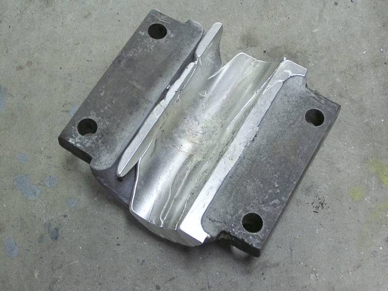
 This time the cap was heated to over 500 ° F and the result was much improved.
This is immediately after removal with no cleanup.
This time the cap was heated to over 500 ° F and the result was much improved.
This is immediately after removal with no cleanup.
The onside cap was done the same way.
 Preheat the shaft and end caps.
 Preheat the cap.
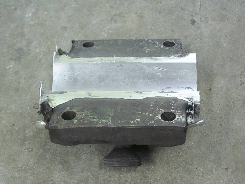
 Quickly bolt the cap in place, install the Babbitt Rite, final heat to 550 °F,
and pour the babbitt. Note the old greaser lower half. The was heated extra hot
and serves as a riser to keep feeding metal as the babbitt solidifies. Note the
babbitt coming out the vents at the upper corners of the bearing. Proof that the
bearing is filled.
Quickly bolt the cap in place, install the Babbitt Rite, final heat to 550 °F,
and pour the babbitt. Note the old greaser lower half. The was heated extra hot
and serves as a riser to keep feeding metal as the babbitt solidifies. Note the
babbitt coming out the vents at the upper corners of the bearing. Proof that the
bearing is filled.
Now its time to do the lowers:
 The same shims that were used to seal the uppers from the lowers were reused to
pour the lowers. But note the slot cut in the upper shims, into which the
babbitt will be poured. The shaft, underside of the shims, endcaps, and collars
were sooted. Notice the soot has been cleared away around the slot. Here pieces
of Babbitt Rite will be stuck after preheating to create both a funnel and a
riser.
The same shims that were used to seal the uppers from the lowers were reused to
pour the lowers. But note the slot cut in the upper shims, into which the
babbitt will be poured. The shaft, underside of the shims, endcaps, and collars
were sooted. Notice the soot has been cleared away around the slot. Here pieces
of Babbitt Rite will be stuck after preheating to create both a funnel and a
riser.
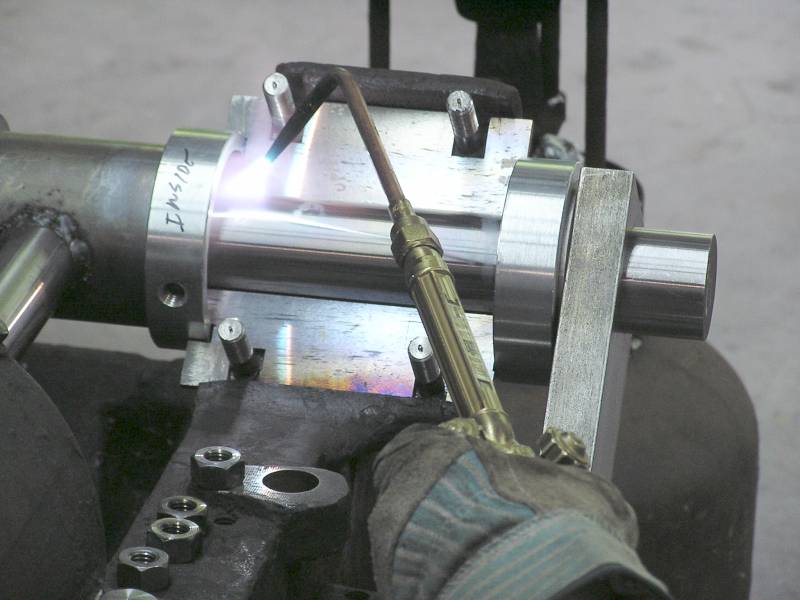
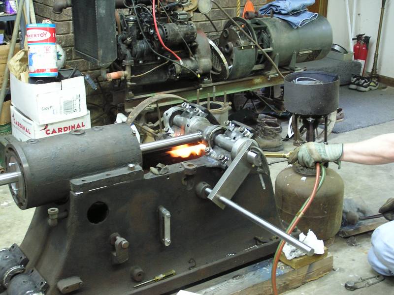 Here preheating of the saddles and everything that will have babbitt poured
against it begins. The target is 550 ° F. In the background the babbitt pot
roars bringing the metal up to proper temperature.
Here preheating of the saddles and everything that will have babbitt poured
against it begins. The target is 550 ° F. In the background the babbitt pot
roars bringing the metal up to proper temperature.
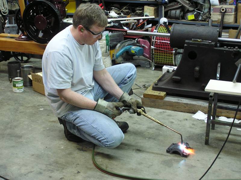
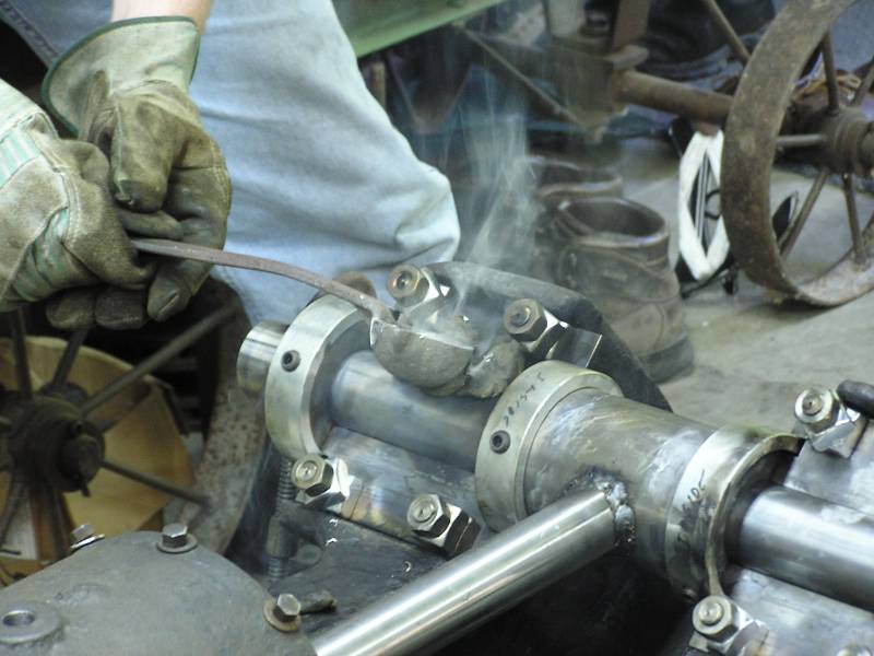 The babbitt is hot enough as a wooden stick chars and ignites when dipped. I'm pouring the off
side bearing.
The babbitt is hot enough as a wooden stick chars and ignites when dipped. I'm pouring the off
side bearing.
 The onside is up to proper temperature and the Babbitt Rite funnel/riser has
been stuck in place. Notice the one on the offside failed and spilled babbitt
:-(
The onside is up to proper temperature and the Babbitt Rite funnel/riser has
been stuck in place. Notice the one on the offside failed and spilled babbitt
:-(
 Pouring the babbitt in the onside bearing. A bigger laddle would help!
 This is how the funnel/riser was supposed to work. No leaks!
 All the pouring fixture has been removed and the risers filed flush with the cap
bed. I'm real pleased with how these turned out. Yes, it is a lot of work to
make the special fixtures to pour the bearings. But this makes for easy scraping
and fitting of the crankshaft!
All the pouring fixture has been removed and the risers filed flush with the cap
bed. I'm real pleased with how these turned out. Yes, it is a lot of work to
make the special fixtures to pour the bearings. But this makes for easy scraping
and fitting of the crankshaft!
 This makes for a leisurely Sunday's work after yesterday's intense pace. Here
the crankshaft is being fitted and the bearings scraped as necessary to give
good fit. Actually the only scraping required was on the outside edge on each
side. A radius was cut on the inside edge and the crankshaft fit right in with
only a couple of hours of work.
This makes for a leisurely Sunday's work after yesterday's intense pace. Here
the crankshaft is being fitted and the bearings scraped as necessary to give
good fit. Actually the only scraping required was on the outside edge on each
side. A radius was cut on the inside edge and the crankshaft fit right in with
only a couple of hours of work.
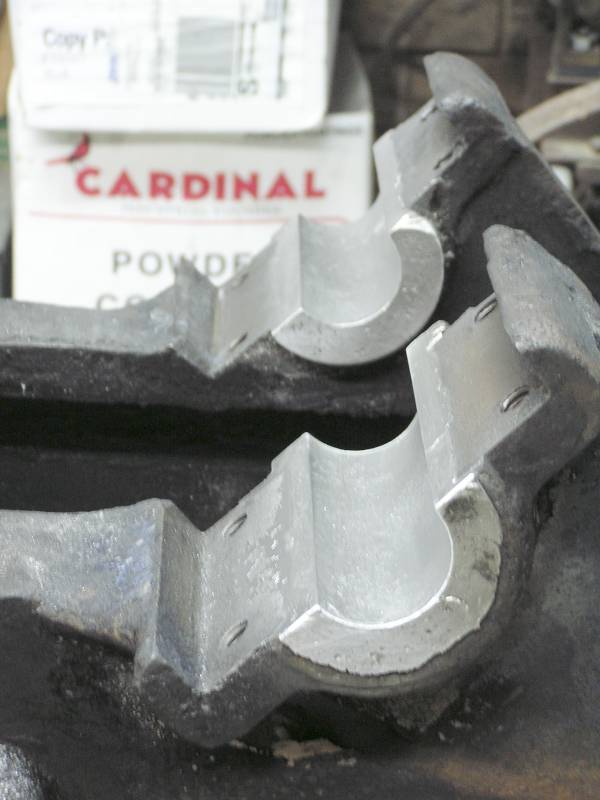
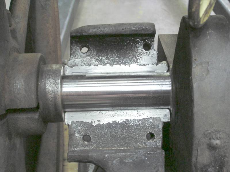 Here is a close-up of the off side bearing. You can just barely see the 45°
chamfer cut in the upper edge. This builds the pressure wedge for the lubricant
film. The chamfer stops about 1/2" from each end. It's not done on the lower
side as the crankshaft doesn't turn that direction.
Here is a close-up of the off side bearing. You can just barely see the 45°
chamfer cut in the upper edge. This builds the pressure wedge for the lubricant
film. The chamfer stops about 1/2" from each end. It's not done on the lower
side as the crankshaft doesn't turn that direction.
Permanent shims will have to be cut for the caps, but other than that these bearings are done. Whew, this is a great ending to a great weekend!
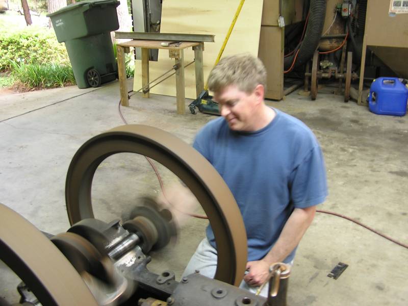 The flywheels spin effortlessly :-)
That's all folks!