Making a core box and pattern for a new piston for a 5HP
Alamo
Click on the thumbnails for a full sized image. Close that
image to return to this page.
1/30/06
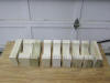
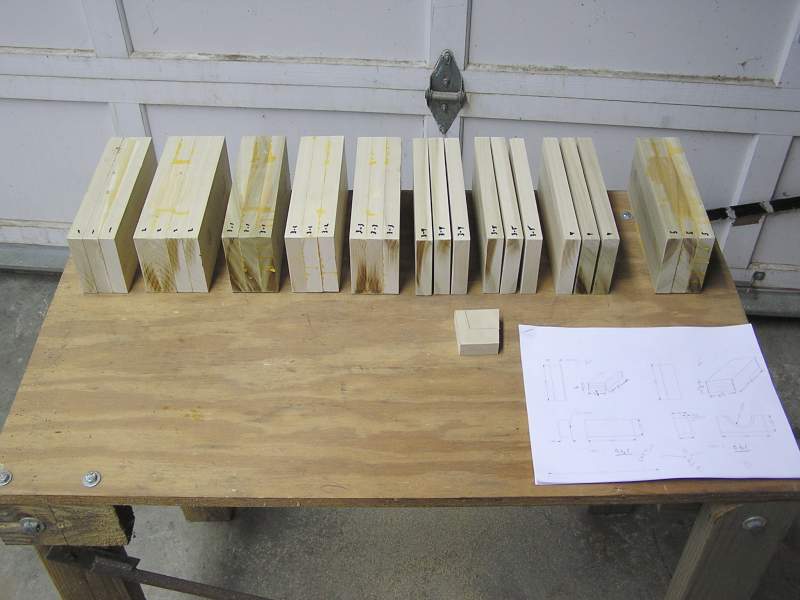
 After drawing the original piston and then scaling it up for shrinkage, drawings
for each 2 1/2" section of the core box were drawn. 3/4" poplar wood was used to
make the 2 1/2" blocks. Friday night I bought the boards and sawed them into
pieces about an 1/8" longer than needed. Then they were glued into blocks of 3
or 4.
After drawing the original piston and then scaling it up for shrinkage, drawings
for each 2 1/2" section of the core box were drawn. 3/4" poplar wood was used to
make the 2 1/2" blocks. Friday night I bought the boards and sawed them into
pieces about an 1/8" longer than needed. Then they were glued into blocks of 3
or 4.
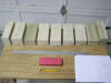 Once dried, the correct diameter/radiuses were swept on each block with a
compass.
Once dried, the correct diameter/radiuses were swept on each block with a
compass.
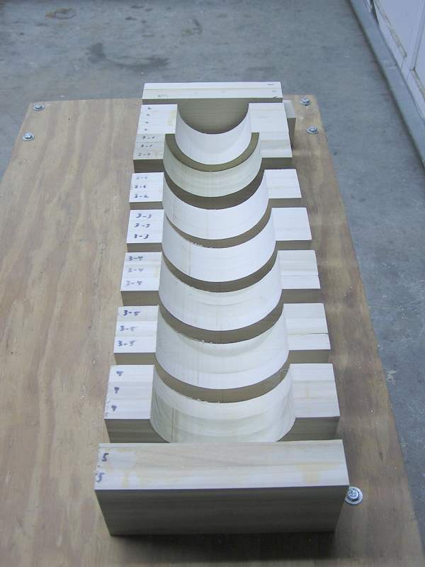
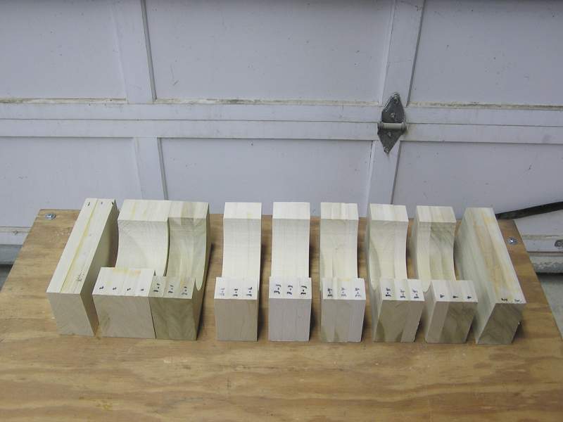
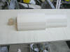
 Sunday afternoon each was cut with a band saw. The blocks on the end are the
caps and are cut with a 2 1/2° or 5° draft.
Sunday afternoon each was cut with a band saw. The blocks on the end are the
caps and are cut with a 2 1/2° or 5° draft.
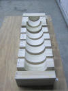
 Another view of the same from the side.
 The new oscillating spindle sander made quick work of making the radiuses smooth
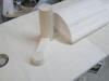
and to size. The table was tilted at 45° and the chamfer on the left was cut.
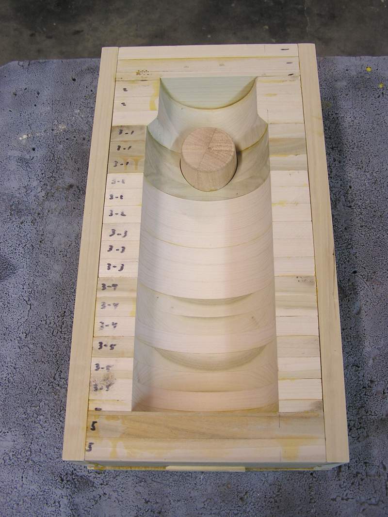
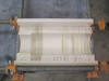
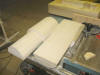
This is the portion of the inside of the piston transitioning between the area
under the rings to the skirt. Late Sunday evening the individual blocks were
glued together and clamped both directions. The boards on the sides were simply
there to keep everything square and are not part of the core box. There is a sheet of wax paper between the sides
and these boards to keep escaping glue from gluing these boards to the core box.
The new oscillating spindle sander made quick work of making the radiuses smooth
and to size. The table was tilted at 45° and the chamfer on the left was cut.
This is the portion of the inside of the piston transitioning between the area
under the rings to the skirt. Late Sunday evening the individual blocks were
glued together and clamped both directions. The boards on the sides were simply
there to keep everything square and are not part of the core box. There is a sheet of wax paper between the sides
and these boards to keep escaping glue from gluing these boards to the core box.
Update 1/31/06:
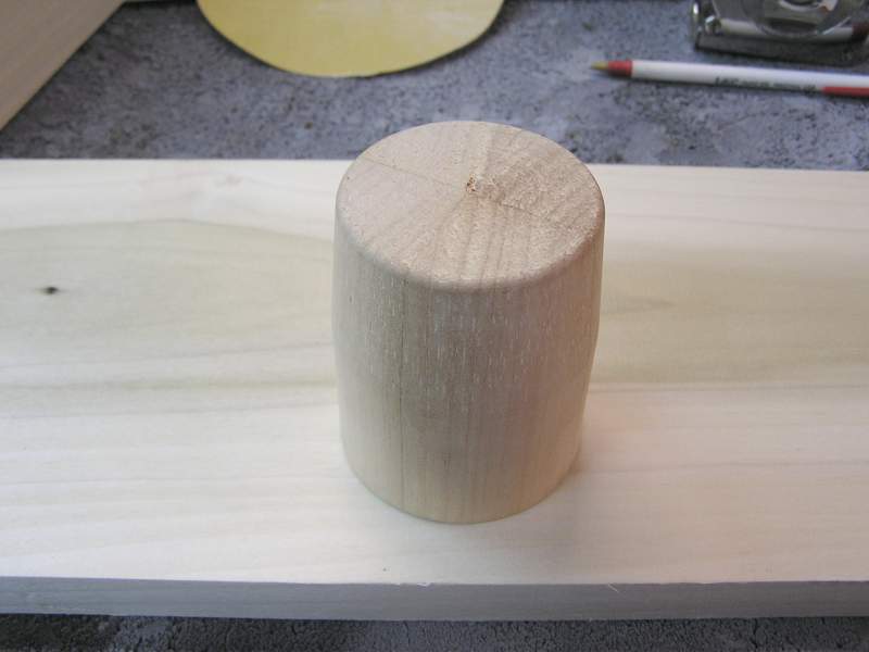
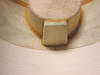
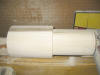
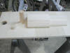
 Monday evening this part was turned. This will form the bosses inside the
piston. Note the bottom half is straight sided where it fits in the core box.
The upper half has 5° draft (per side) to aide release.
Monday evening this part was turned. This will form the bosses inside the
piston. Note the bottom half is straight sided where it fits in the core box.
The upper half has 5° draft (per side) to aide release.
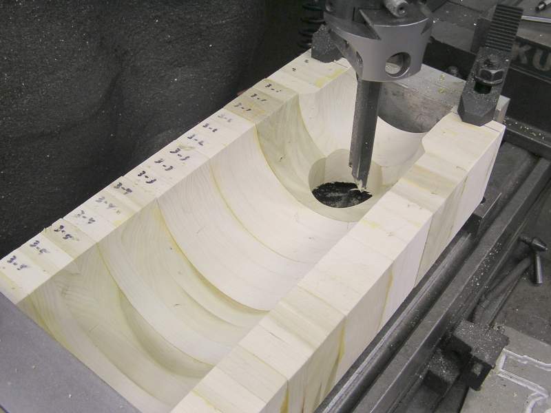
 The core box was set up in the mill and the hole bored for the boss to fit into.
First a hole was drilled and then a boring head was used to get out to the 2
1/2" diameter.
The core box was set up in the mill and the hole bored for the boss to fit into.
First a hole was drilled and then a boring head was used to get out to the 2
1/2" diameter.
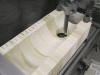
 Here everything has been glued together. Everything was set on a piece of 3/4"
plywood and also the 3/4 boards have been glued along the sides for additional
stability.
Here everything has been glued together. Everything was set on a piece of 3/4"
plywood and also the 3/4 boards have been glued along the sides for additional
stability.
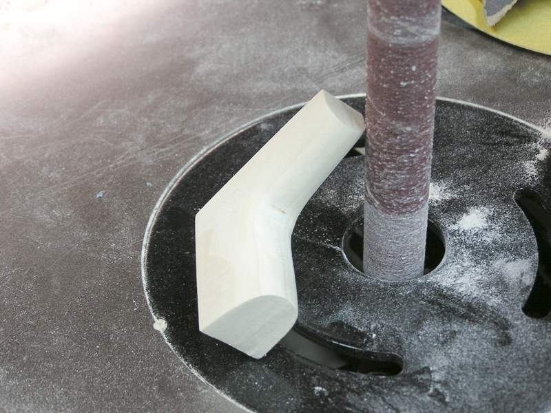
 This little piece forms the web from the top of the boss and under the crown of
the piston. This part has to be made entirely by hand. Cut out with a coping saw
and all the curves and draft done with a file and sandpaper.
This little piece forms the web from the top of the boss and under the crown of
the piston. This part has to be made entirely by hand. Cut out with a coping saw
and all the curves and draft done with a file and sandpaper.
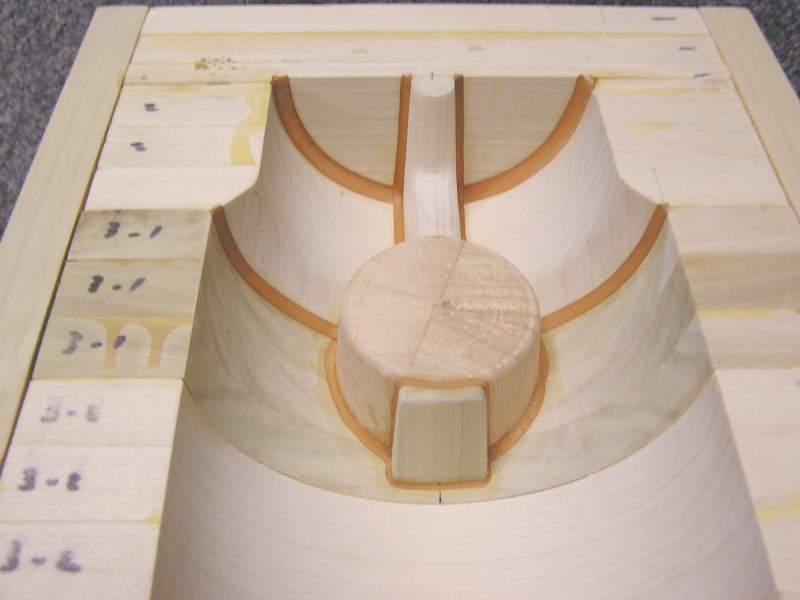
 And finally the web has been glued in. These 5 steps took about 5 hours last
night. This brings the total work time to about 11 hours so far.
And finally the web has been glued in. These 5 steps took about 5 hours last
night. This brings the total work time to about 11 hours so far.
Update 2/2/06:
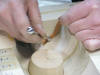 Didn't get to work in the shop Tuesday evening but got a couple of hours in on
Wednesday evening. Missy took this picture as I was starting to put the leather
fillets in. The ball ended forming tools from Freeman Supply really make the
fillets turn out great. Way better than using a rounded stick :-)
Didn't get to work in the shop Tuesday evening but got a couple of hours in on
Wednesday evening. Missy took this picture as I was starting to put the leather
fillets in. The ball ended forming tools from Freeman Supply really make the
fillets turn out great. Way better than using a rounded stick :-)
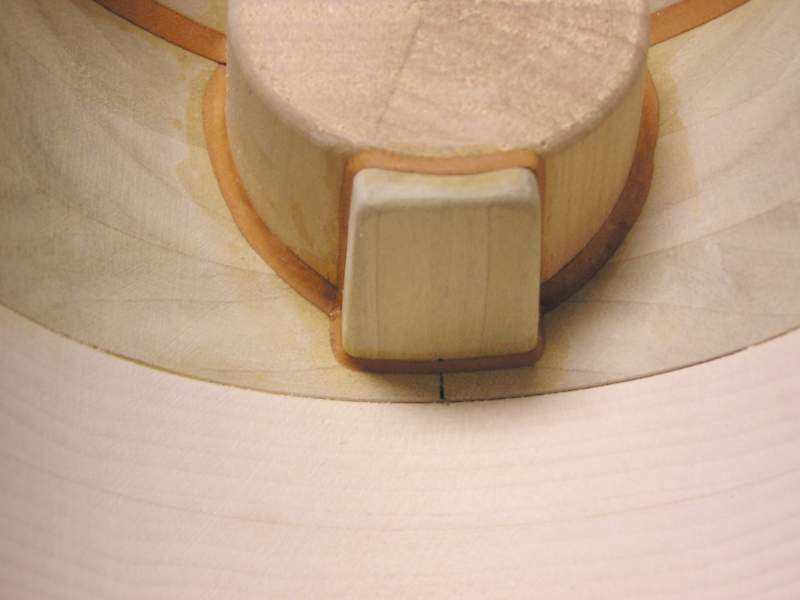
 The last piece I needed to make was this tab that fits on the back of the boss.
Once machined the locking nut for the wrist pin bolt will tighten against this
tab.
The last piece I needed to make was this tab that fits on the back of the boss.
Once machined the locking nut for the wrist pin bolt will tighten against this
tab.
 At the core print end a large fillet was installed to assure no interference
with the pattern.
At the core print end a large fillet was installed to assure no interference
with the pattern.
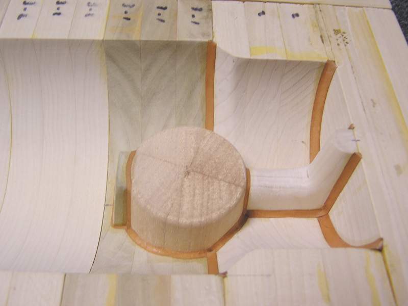
 For the area inside the piston there are 3 sizes of fillet used. Basically you
choose the size by what looks good! I've tried using body filler to make the
fillets before, but the leather is much easier. Besides with leather you get way more respect from
fellow pattern makers too!
For the area inside the piston there are 3 sizes of fillet used. Basically you
choose the size by what looks good! I've tried using body filler to make the
fillets before, but the leather is much easier. Besides with leather you get way more respect from
fellow pattern makers too!
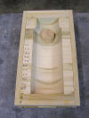
 And a view of the same from the side. That's it! A total of 13 hours so far, and
other than a coat of yellow paint (standard foundry color for core boxes and
core prints), this core box is done. By far this is the hardest part of making a
piston pattern. So if you need a piston for one of your engines, making a core
box is really a fairly easy process.
And a view of the same from the side. That's it! A total of 13 hours so far, and
other than a coat of yellow paint (standard foundry color for core boxes and
core prints), this core box is done. By far this is the hardest part of making a
piston pattern. So if you need a piston for one of your engines, making a core
box is really a fairly easy process.
Update 2/13/06:
With the core box work behind it was time to make the pattern which forms the
outside profile of the piston. To make the block the pattern would be turned
from 2 blocks were glued up from 3/4" boards. The the two blocks were spot glued
together. About 6 dots of glue a 1/4" in diameter at random and about a 1/4"
strip at each end were all that held the two blocks together. About 1 hour was
spent cutting and gluing the boards into blocks.
 The glued block measuring about 7 1/2" square x 16" long was chucked up in a
home made wood lathe belonging to friend Bill Baker. Though quite slow compared
to a metal lathe, the advantage of a wood lathe is that you can get the center
on the drive end exactly where the two half blocks come together. It took nearly
5 hours to get this block from square to round and to size, so a manual wood
lathe is not very fast compared to a metal lathe.
The glued block measuring about 7 1/2" square x 16" long was chucked up in a
home made wood lathe belonging to friend Bill Baker. Though quite slow compared
to a metal lathe, the advantage of a wood lathe is that you can get the center
on the drive end exactly where the two half blocks come together. It took nearly
5 hours to get this block from square to round and to size, so a manual wood
lathe is not very fast compared to a metal lathe.
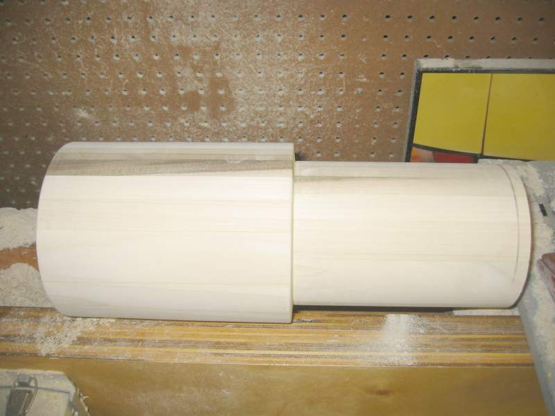
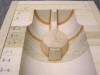
 A light tap with a wide chisel at the glue line was all it took to separate the
two halves again. The larger diameter is the OD of the piston and the smaller
diameter creates the core print. This will tightly support the core created by
the bore box. The core print is as long as the core projects into the piston to
hopefully provide more support than other piston patterns I have made. When one
looks at the volume the core displaces and the density of cast iron, there is
nearly 40# of buoyancy force to content with! That necessitates considerable
support of the core.
A light tap with a wide chisel at the glue line was all it took to separate the
two halves again. The larger diameter is the OD of the piston and the smaller
diameter creates the core print. This will tightly support the core created by
the bore box. The core print is as long as the core projects into the piston to
hopefully provide more support than other piston patterns I have made. When one
looks at the volume the core displaces and the density of cast iron, there is
nearly 40# of buoyancy force to content with! That necessitates considerable
support of the core.
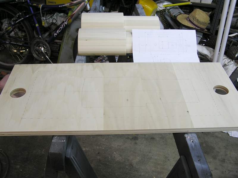
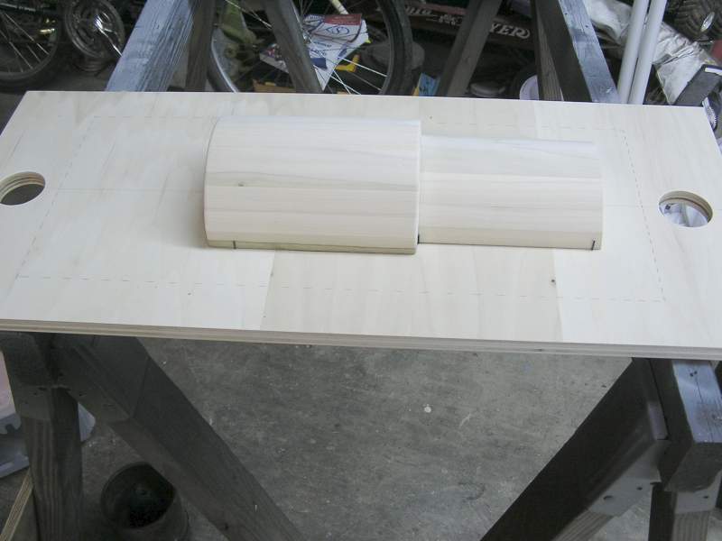
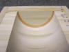
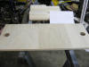 At this point it is important to have a conversation with the foundry of your
choice and determine what the size of the flask is that they will be using to
ram your pattern with. The piece of 3/4" plywood is cut and the 2" holes spaced
to fit the interlocks on the flask latches. Looking closely you will see a
dashed line profiling the inside of the flask. Also traced in solid is where the
pattern will be mounted. This will be gated and risered on the crown end of the
piston so a little extra room is needed on the crown end. This is why the
pattern is positioned to the right a little.
At this point it is important to have a conversation with the foundry of your
choice and determine what the size of the flask is that they will be using to
ram your pattern with. The piece of 3/4" plywood is cut and the 2" holes spaced
to fit the interlocks on the flask latches. Looking closely you will see a
dashed line profiling the inside of the flask. Also traced in solid is where the
pattern will be mounted. This will be gated and risered on the crown end of the
piston so a little extra room is needed on the crown end. This is why the
pattern is positioned to the right a little.
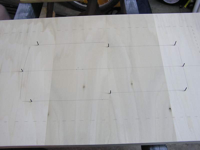
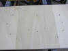 There are several methods that can be used to align the upper and lower halves.
Once the outline of the pattern is centered and traced on the board, I drill a
series of 1/16" holes around the perimeter. You can use 1/16 pins or I just use
several 1/16" drill bit sticking out each side of the board about a 1/2".
There are several methods that can be used to align the upper and lower halves.
Once the outline of the pattern is centered and traced on the board, I drill a
series of 1/16" holes around the perimeter. You can use 1/16 pins or I just use
several 1/16" drill bit sticking out each side of the board about a 1/2".
 The pattern has been glued to the board, nested tightly between the 1/16" drill
bits. Once the glue is dried the board will be flipped over and the other half
glued on as well.
The pattern has been glued to the board, nested tightly between the 1/16" drill
bits. Once the glue is dried the board will be flipped over and the other half
glued on as well.
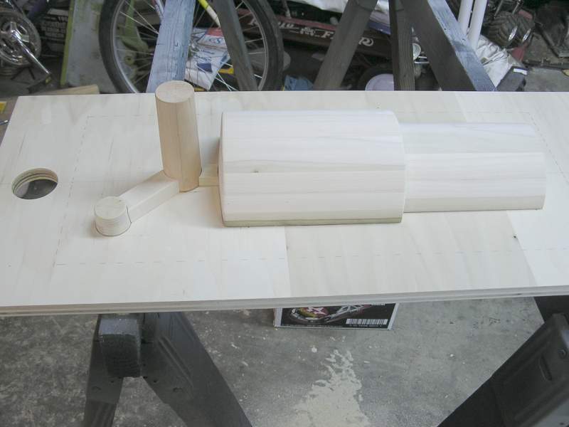
 Now that both halves of the pattern are glued to the board it is time to add the
gates, riser, and sprue runner.
Now that both halves of the pattern are glued to the board it is time to add the
gates, riser, and sprue runner.
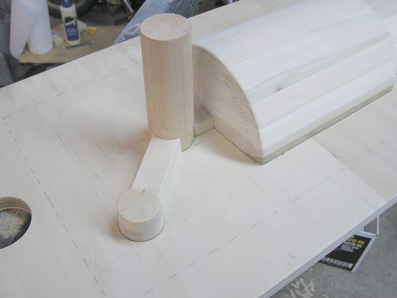
 A close up of the same, the cope side of the pattern.
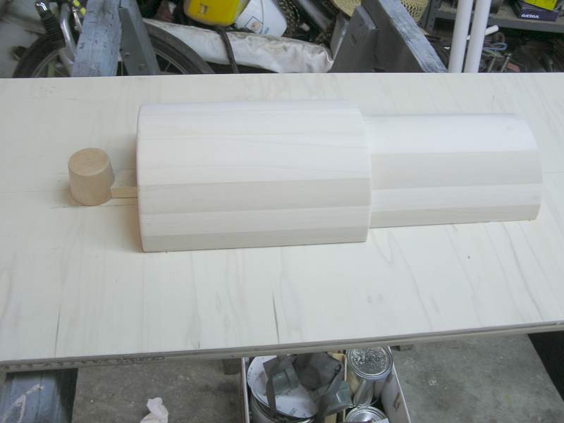
 The board has been turned over to see the projection directly under the riser on
the drag side. The pattern is finished and a coat of paint will be applied.
The board has been turned over to see the projection directly under the riser on
the drag side. The pattern is finished and a coat of paint will be applied.
Approximately 5 hours was spent mounting the split pattern on board and
adding the metal path. So in total about 10 hours was spent on the pattern.
There were 13 hours in the core box making the project total hours about 23.
Total materials cost was just over a $100. Pretty decent investment to get a
brand new part that you can turn to the exact diameter needed. And when your
friends need the same piston for their engine you'll be able to help them out!
Hope you've enjoyed this series of photos.
Curt
5/2/06 Update:
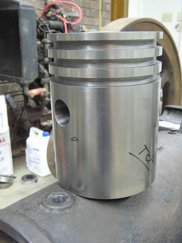
 Here is the piston all machined and ready for installation in the engine.
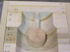
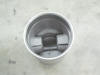 And a picture of the inside. Just need to drill and tap the wrist pin holes.
 After drawing the original piston and then scaling it up for shrinkage, drawings
for each 2 1/2" section of the core box were drawn. 3/4" poplar wood was used to
make the 2 1/2" blocks. Friday night I bought the boards and sawed them into
pieces about an 1/8" longer than needed. Then they were glued into blocks of 3
or 4.
After drawing the original piston and then scaling it up for shrinkage, drawings
for each 2 1/2" section of the core box were drawn. 3/4" poplar wood was used to
make the 2 1/2" blocks. Friday night I bought the boards and sawed them into
pieces about an 1/8" longer than needed. Then they were glued into blocks of 3
or 4.