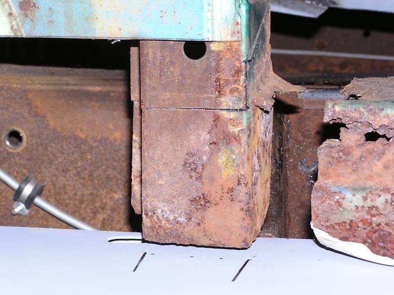
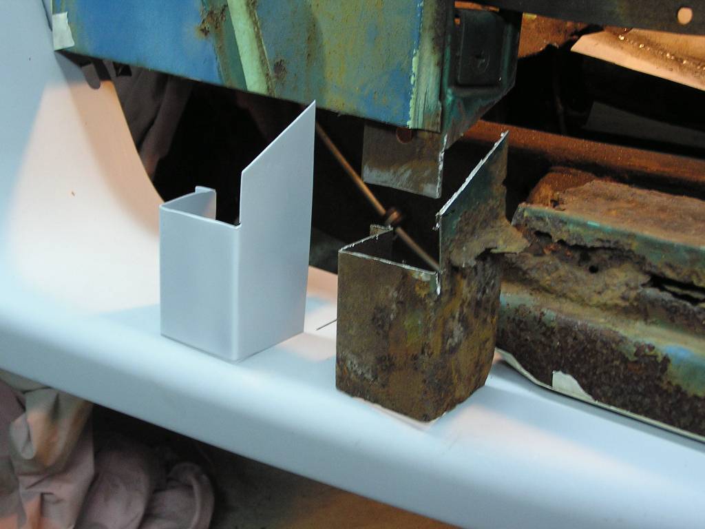
 The cover over the transmission access hole is even rusted away on the lower
edges. Will have to replace the bottom 3 or 4 inches on each side. You can see
the patch panel I've made, and the cut line on the part.
The cover over the transmission access hole is even rusted away on the lower
edges. Will have to replace the bottom 3 or 4 inches on each side. You can see
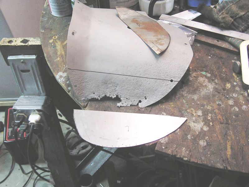
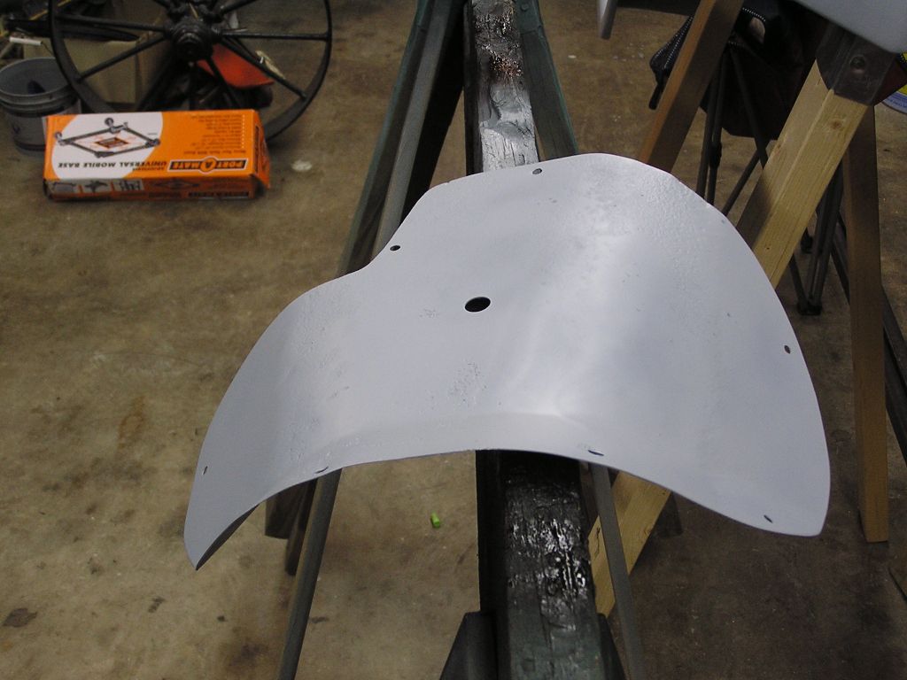
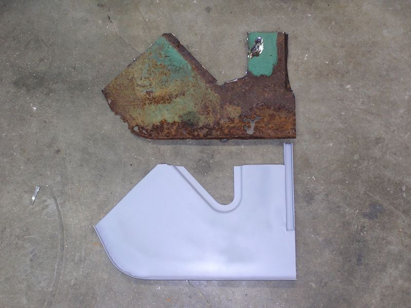
the patch panel I've made, and the cut line on the part. Cover over the transmission access:
The cover over the transmission access hole is even rusted away on the lower
edges. Will have to replace the bottom 3 or 4 inches on each side. You can see
the patch panel I've made, and the cut line on the part.
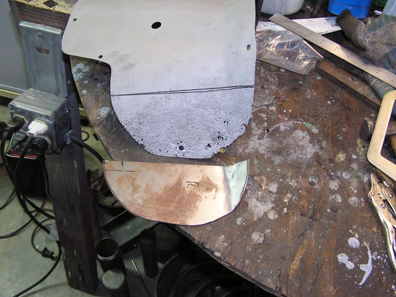 Same style patch repair for the passenger side of the cover.
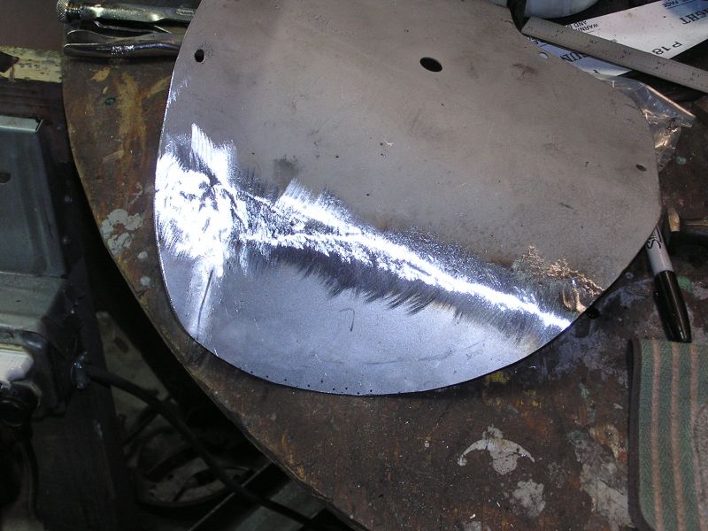 An hour later and both sides are welded in, ground flush, and ready for paint.
This is the driver's side.
An hour later and both sides are welded in, ground flush, and ready for paint.
This is the driver's side.
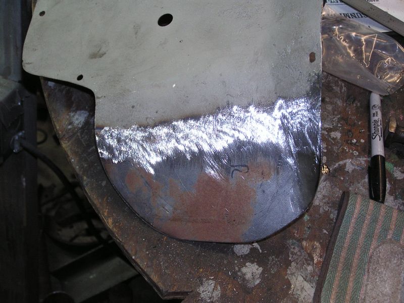 And the passenger side repair completed.
 After drilling the screw holes a final sandblasting is done, it is primed with
self etching primer and this part is as good as new.
After drilling the screw holes a final sandblasting is done, it is primed with
self etching primer and this part is as good as new.
Passenger's side floor pan replacement:
3/13/09
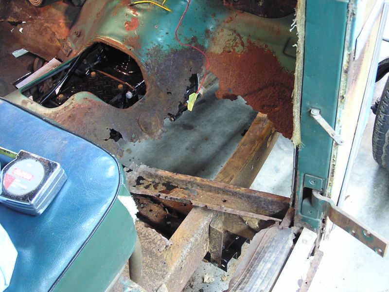 OH NO! We removed the rubber mats on the
passenger side and found nothing underneath it!
OH NO! We removed the rubber mats on the
passenger side and found nothing underneath it!
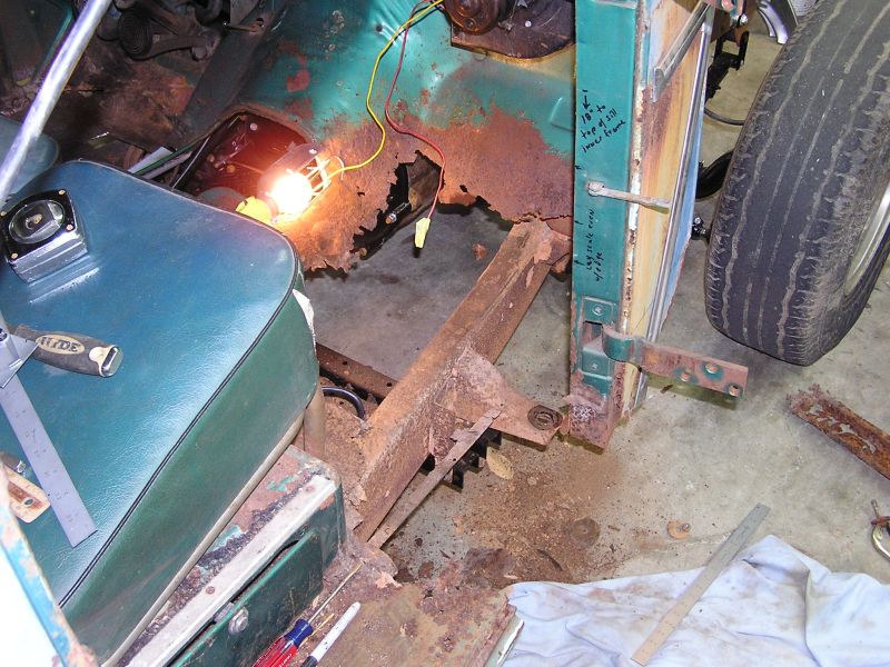 Here we have cut the front half of the rocker panel and inner frame member away
to gain access to the inner cowl panel.
Here we have cut the front half of the rocker panel and inner frame member away
to gain access to the inner cowl panel.
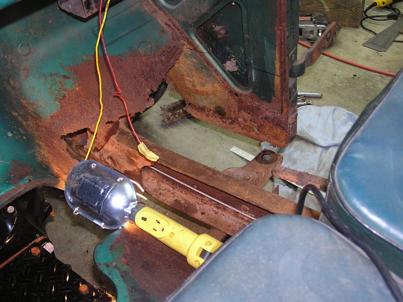 Despite the heavy rust that made most of the right pan disappear, the inner cowl
panel is nearly in tack!!! This will make creating the replacement much easier
as we have something to follow. It's interesting that on the driver's side,
where the floorboards are in much better shape, this inner cowl panel is
completely rusted away. How strange. Some CAD layouts were done and a sample cut
from cardboard. This fit nicely so we marked up the sheet metal and began
cutting and welding to make the replacement inner cowl panel.
Despite the heavy rust that made most of the right pan disappear, the inner cowl
panel is nearly in tack!!! This will make creating the replacement much easier
as we have something to follow. It's interesting that on the driver's side,
where the floorboards are in much better shape, this inner cowl panel is
completely rusted away. How strange. Some CAD layouts were done and a sample cut
from cardboard. This fit nicely so we marked up the sheet metal and began
cutting and welding to make the replacement inner cowl panel.
3/16/09
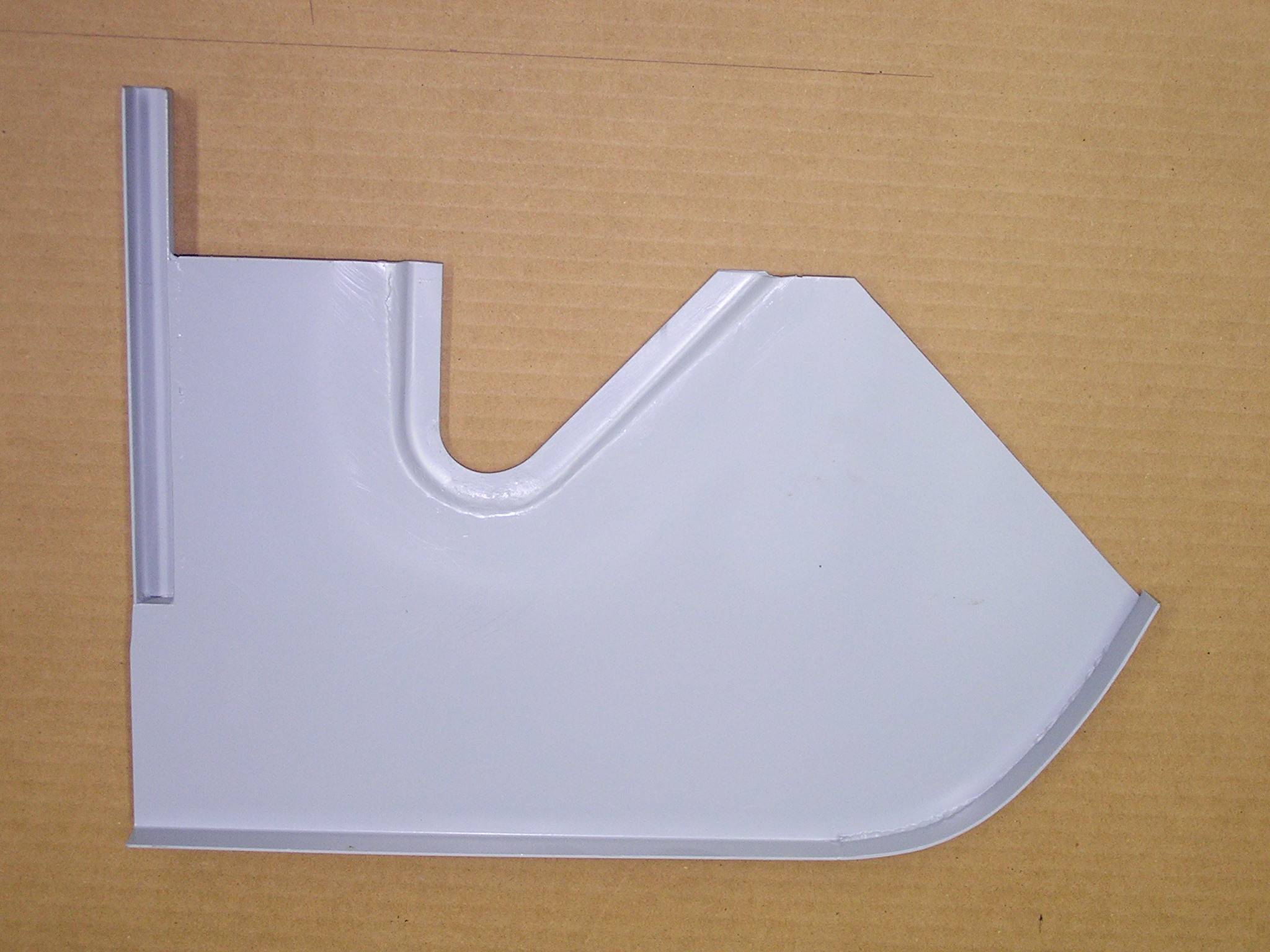
 Here is the new inner cowl panel we fab'd from scratch. Note the small square
trough on the right. This holds the packing material that interior trim will be
stapled to. The original inner cowl is above showing how badly rusty and thin it
was.
Here is the new inner cowl panel we fab'd from scratch. Note the small square
trough on the right. This holds the packing material that interior trim will be
stapled to. The original inner cowl is above showing how badly rusty and thin it
was.
 Before welding in the inner cowl panel, we cut off the lower 5" of the door post
and welded in this new section. The post wasn't rusted thru, but was mighty
thin. This was the time to do it, while we still had access to the inside of the
post to weld.
Before welding in the inner cowl panel, we cut off the lower 5" of the door post
and welded in this new section. The post wasn't rusted thru, but was mighty
thin. This was the time to do it, while we still had access to the inside of the
post to weld.
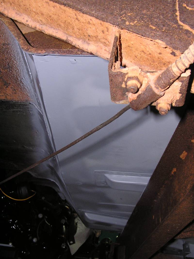
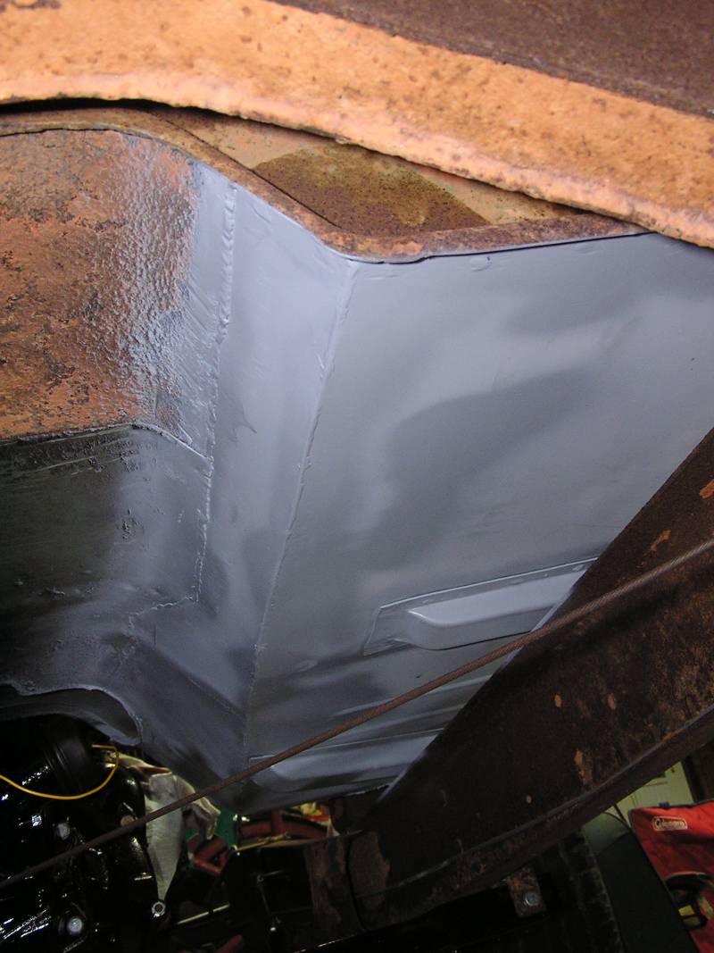
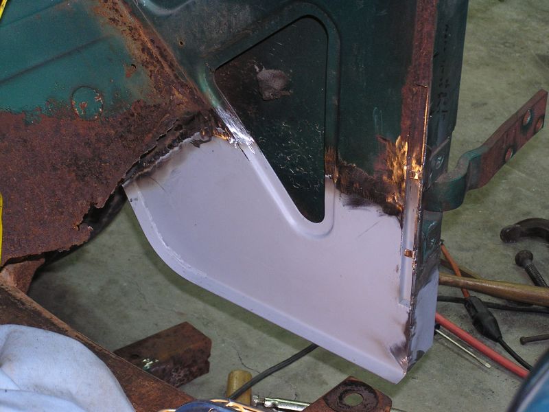 And here is the view inside showing the completed welding and grinding of the
inner cowl panel. Notice we even retained the strengthening profile around the
triangular cutout. Yes it is overkill for something that will be covered with an
interior trim panel, but it makes for a professional repair.
And here is the view inside showing the completed welding and grinding of the
inner cowl panel. Notice we even retained the strengthening profile around the
triangular cutout. Yes it is overkill for something that will be covered with an
interior trim panel, but it makes for a professional repair.
3/24/09
 We just keep digging our way towards the back trying to find the end of the
rusty floor pan. Finally we are at the cross beam behind the seats. All the spot
welds are cut loose and the last of the rusty floor pan is out!
We just keep digging our way towards the back trying to find the end of the
rusty floor pan. Finally we are at the cross beam behind the seats. All the spot
welds are cut loose and the last of the rusty floor pan is out!
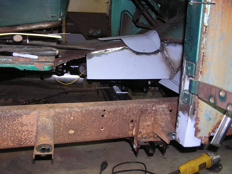 Here you can see where we've started welding in the repair pieces going up into
the transmission tunnel.
Here you can see where we've started welding in the repair pieces going up into
the transmission tunnel.
 Ahh things are starting to look a little better! The main pan is in and tacked
in place along with the rocker panel being temporarily held in place with a
couple of rivets.
Ahh things are starting to look a little better! The main pan is in and tacked
in place along with the rocker panel being temporarily held in place with a
couple of rivets.
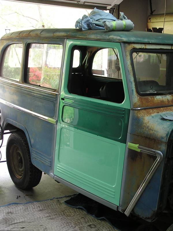
 Here we have installed the completed door to check fit and alignment. The lower
part of the door post is moved in or out to accomplish door alignment with the
back part of the cab. Once set the lower door post is welded to the floor pan.
Here we have installed the completed door to check fit and alignment. The lower
part of the door post is moved in or out to accomplish door alignment with the
back part of the cab. Once set the lower door post is welded to the floor pan.
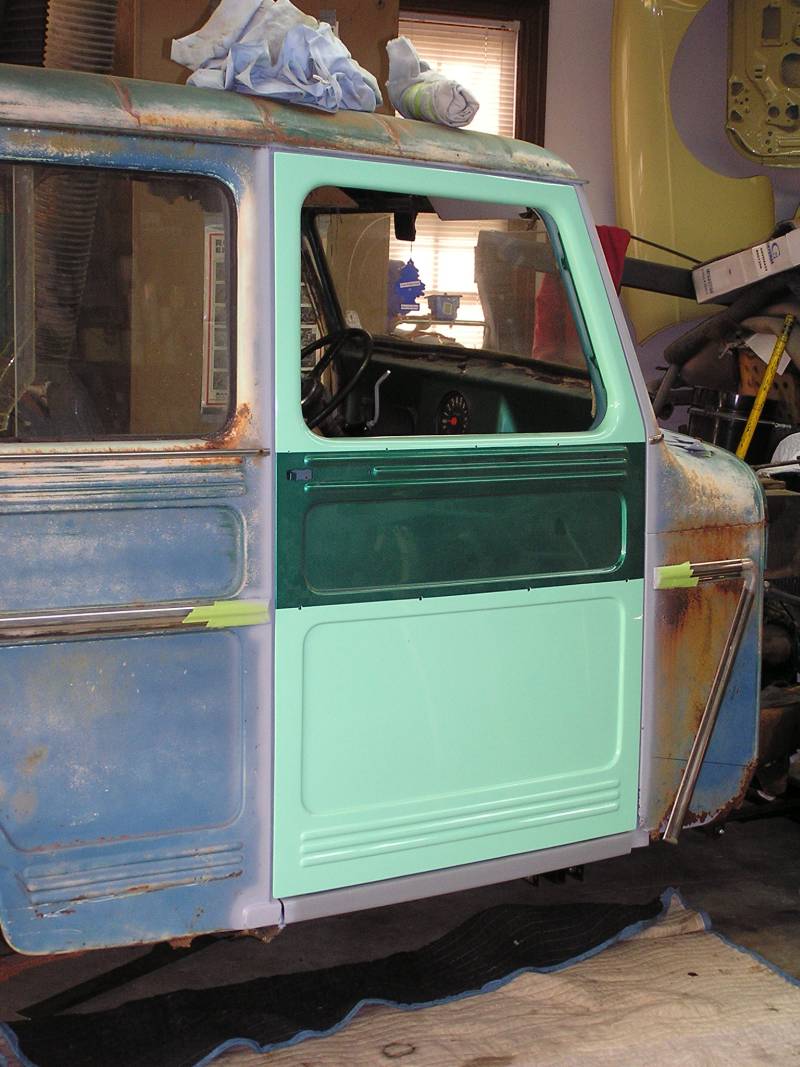
 And a photo from the front of the door in good alignment. Pretty exciting to see
these coming together!
And a photo from the front of the door in good alignment. Pretty exciting to see
these coming together!
4/13/08
 Before we get too far along, we needed to replace the bottom 4" of the door post
at the rear. Here the old part has been cut, being careful not to damage the
quarter panel. The old section wasn't rusted thru yet, but it was thin.
Before we get too far along, we needed to replace the bottom 4" of the door post
at the rear. Here the old part has been cut, being careful not to damage the
quarter panel. The old section wasn't rusted thru yet, but it was thin.
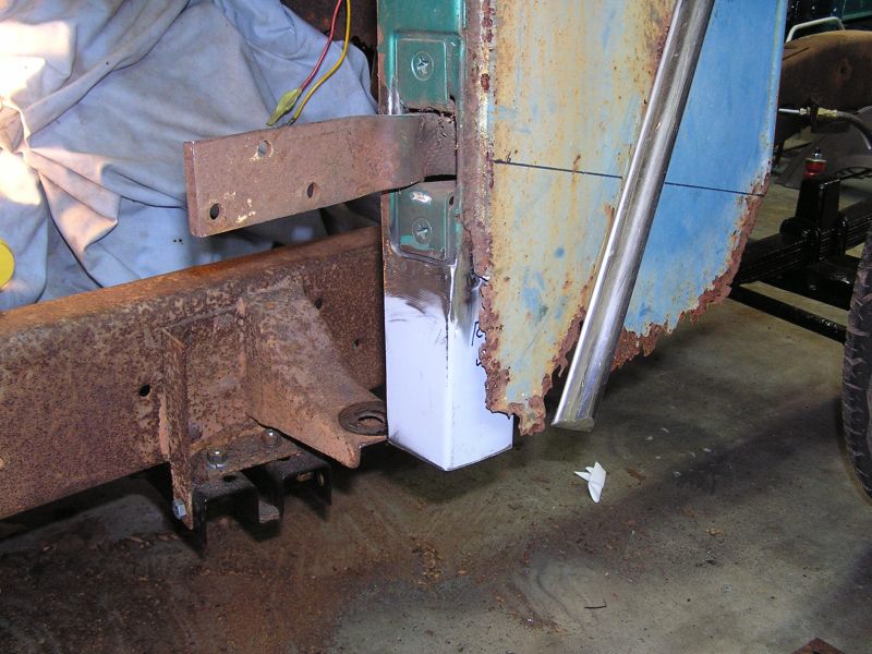
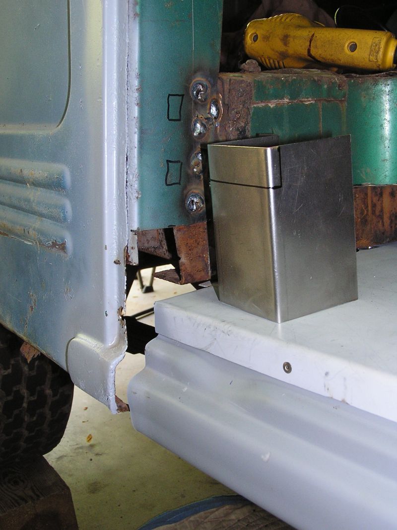
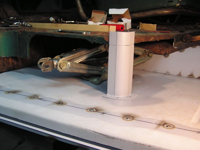
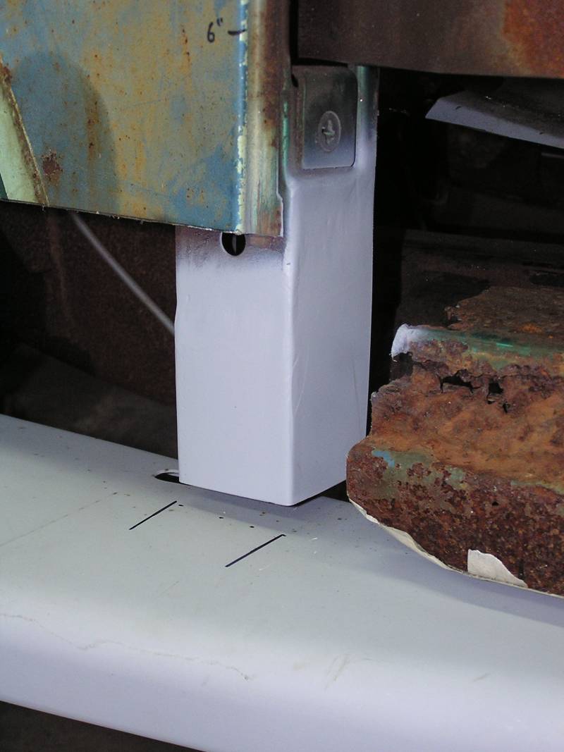
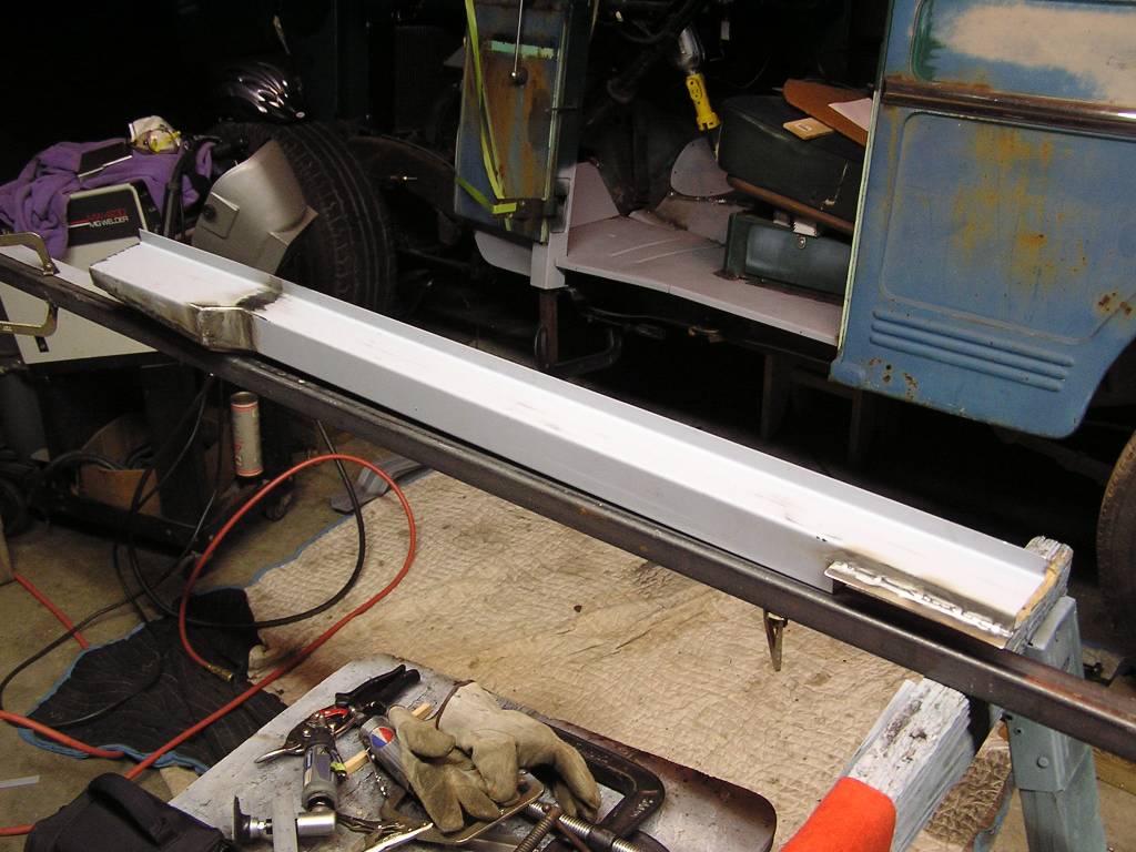
 Well I got fed up with yet another aftermarket part not fitting and decided to
just make my own. The one I made, in the foreground, is the correct height at
the back (left side) at 3.06" tall. The aftermarket ones are much less tall at
the back, and they won't fit properly under the door post at the back.
Well I got fed up with yet another aftermarket part not fitting and decided to
just make my own. The one I made, in the foreground, is the correct height at
the back (left side) at 3.06" tall. The aftermarket ones are much less tall at
the back, and they won't fit properly under the door post at the back.
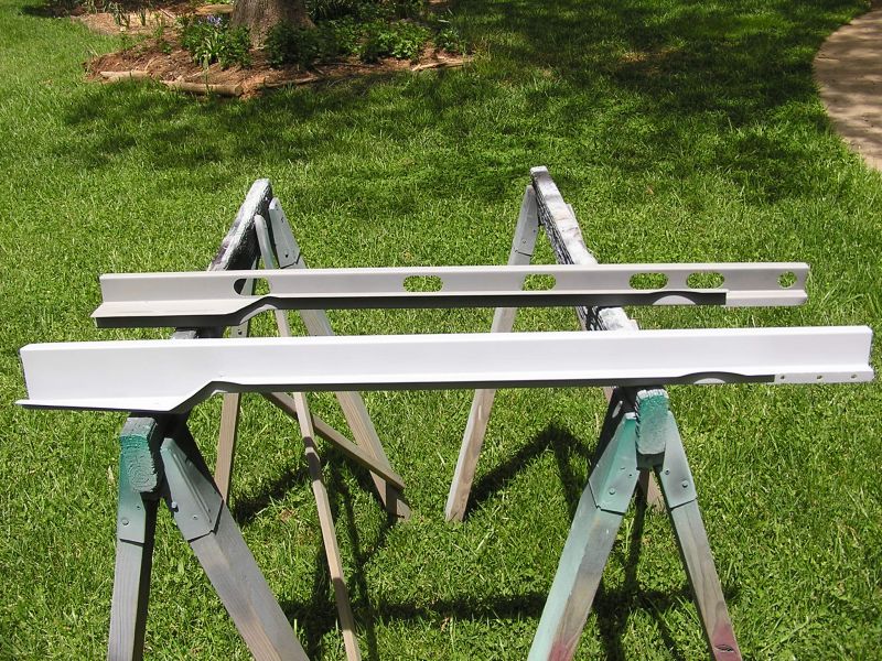
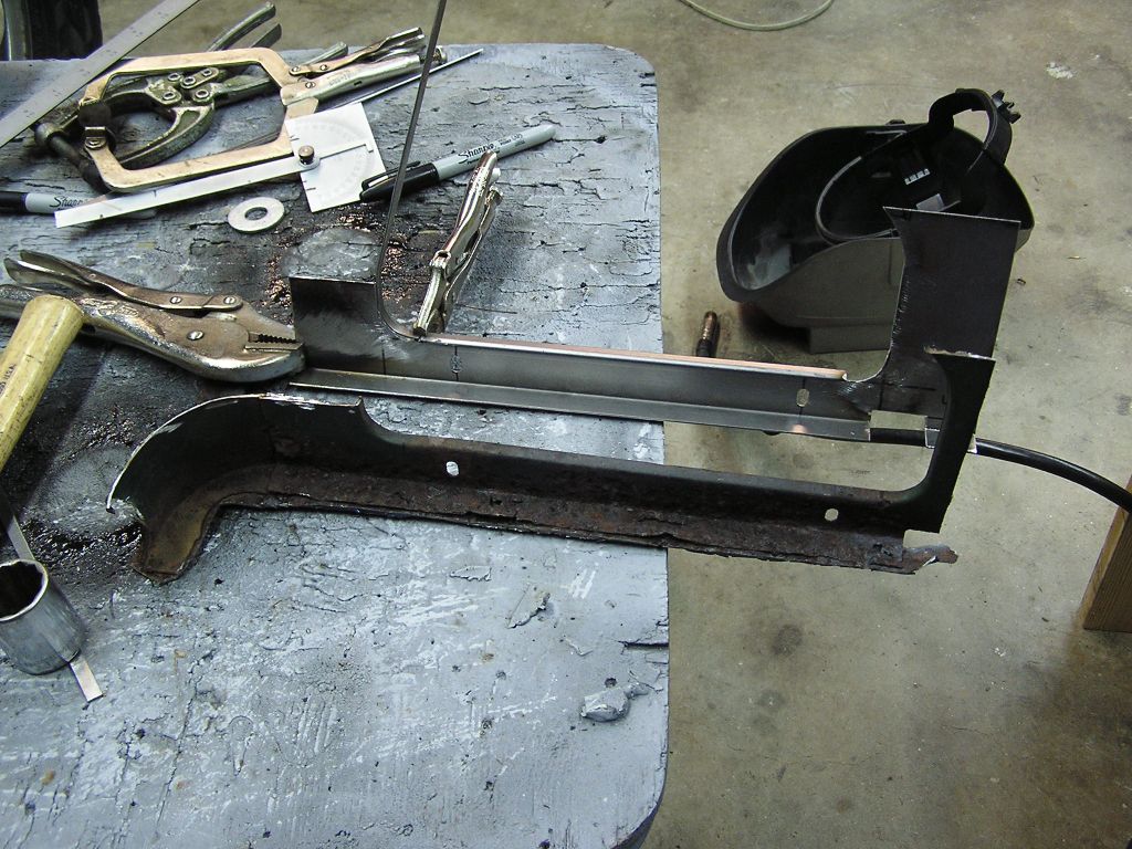
 A different view of the same. Notice the taper on the one I made at the left
end? This closely replicates the original shape. The aftermarket ones don't do
this and therefore can't properly support the lower edge of the quarter panel.
A different view of the same. Notice the taper on the one I made at the left
end? This closely replicates the original shape. The aftermarket ones don't do
this and therefore can't properly support the lower edge of the quarter panel.
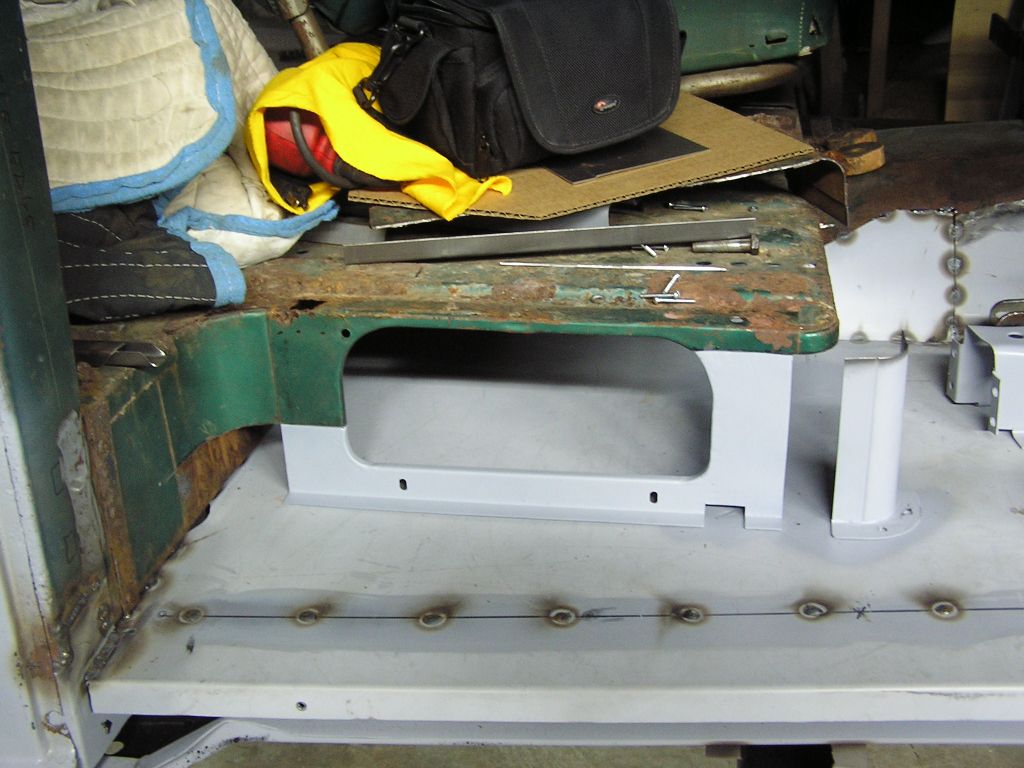
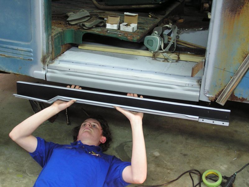 Here Devin is getting ready to place the new beam under the bottom of the floor
pan just behind the rocker panel. You'll see a row of drilled holes in the floor
pan about 3" from the edge. These will be the plug welds holding the floor pan
to this beam. We undercoated the inside of the beam before installing it for
rust prevention.
Here Devin is getting ready to place the new beam under the bottom of the floor
pan just behind the rocker panel. You'll see a row of drilled holes in the floor
pan about 3" from the edge. These will be the plug welds holding the floor pan
to this beam. We undercoated the inside of the beam before installing it for
rust prevention.
 Plug welding the beam and floor pan together.
4/20/08 thru 5/7/09 Several weeks of productive time were lost to some other projects. The Ford truck needed new ball joints on it and time was spent getting an old gas engine running for a friend. We are back on the Willys project now.
<Photo>
Now that the floor boards were in we needed to install the cross supports under the floor pan that attach the pan to the frame. These two aftermarket parts were of course with their mistakes and a little cutting and welding was required to make them fit properly. It wasn't too bad. This picture is from the underside showing the two beams in place.
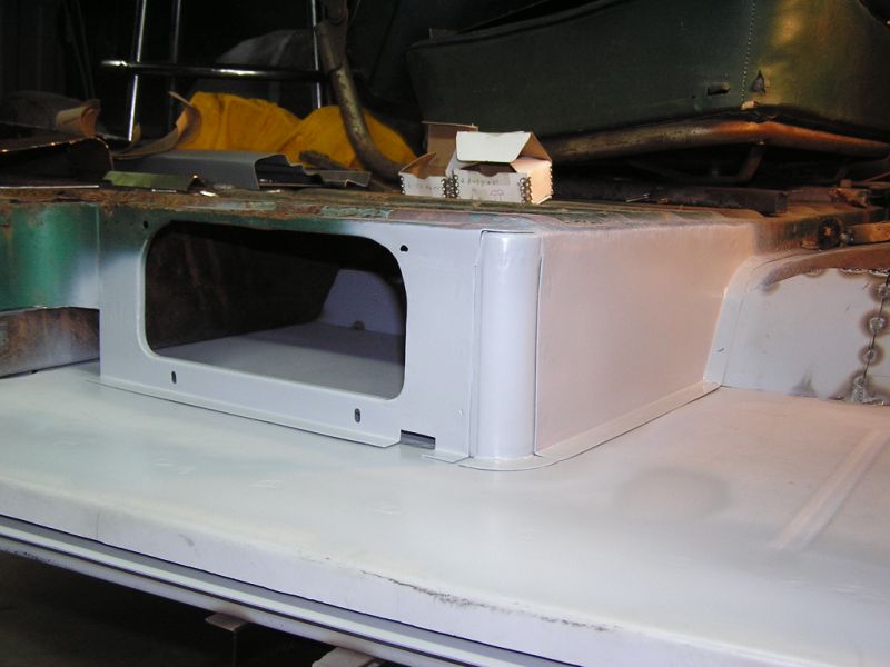
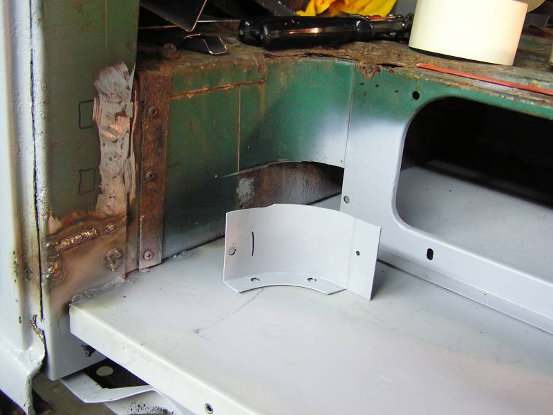
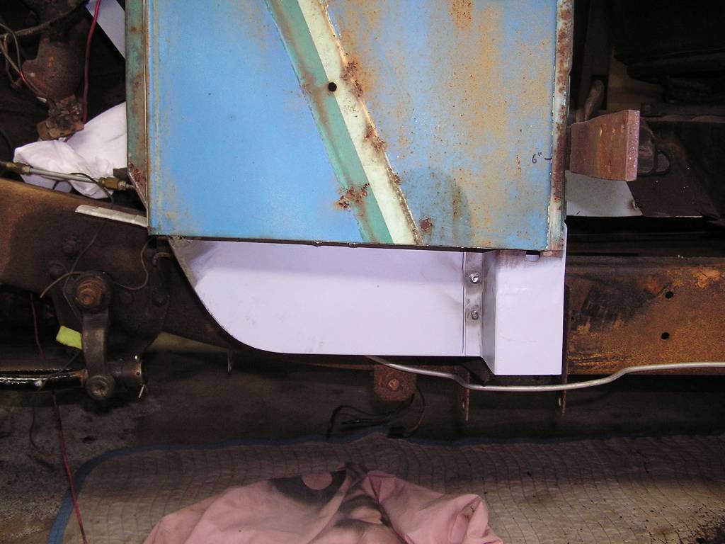
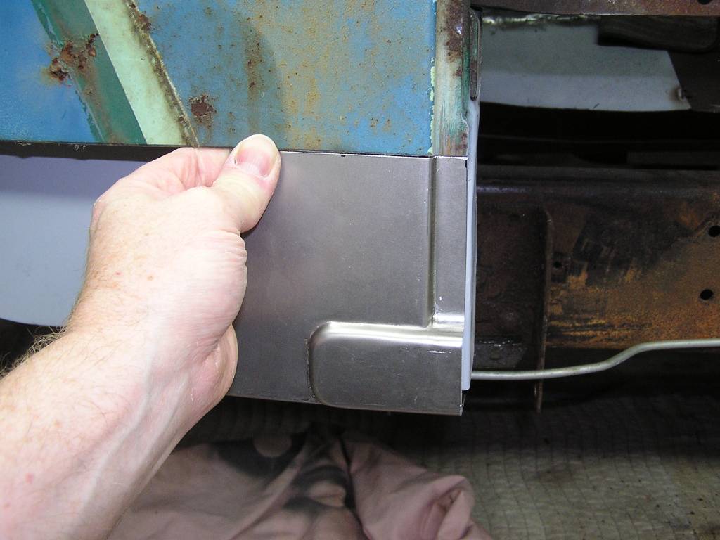
 Now that the floor pans were all tacked in place it was time to start remaking
the pieces to close in the box riser that supports the cargo floor. This corner
piece was made by simply pressing the sheet metal with a round bar of 1 3/4
diameter, with a piece of 1" urethane rubber behind the sheet metal. Was shocked
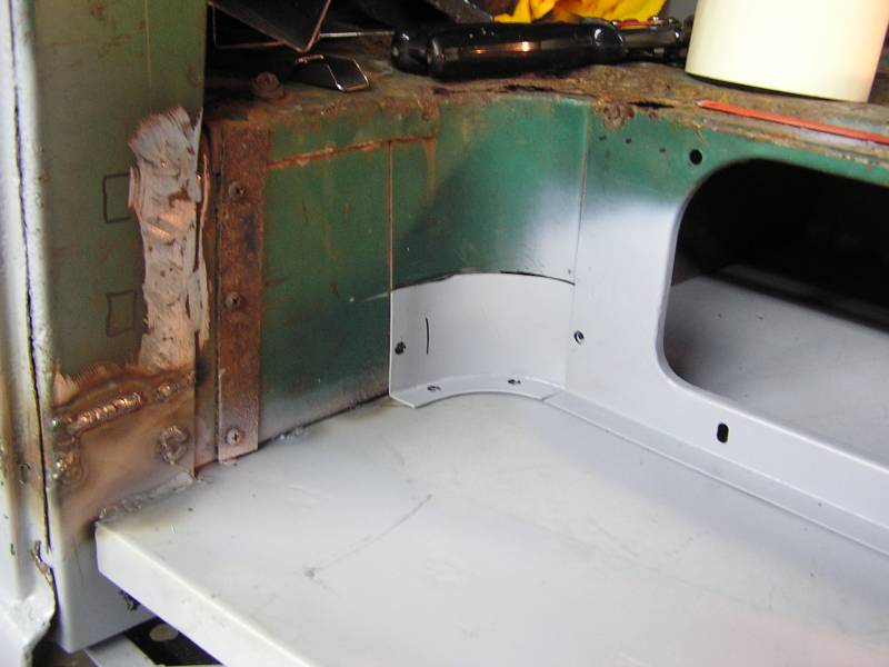
how easy this was! We are marking it off as to where to cut in and will weld it
in in a moment.
Now that the floor pans were all tacked in place it was time to start remaking
the pieces to close in the box riser that supports the cargo floor. This corner
piece was made by simply pressing the sheet metal with a round bar of 1 3/4
diameter, with a piece of 1" urethane rubber behind the sheet metal. Was shocked
how easy this was! We are marking it off as to where to cut in and will weld it
in in a moment.
5/20/09
 Here we are making the seat riser between the floor pan and the cargo floor.
This part was originally stamped creating the 1/4" lip around. Here a 1/4" strip
is being welded to the rest of the formed part. This was made from about 5
pieces welded together. The rusty original is in front.
Here we are making the seat riser between the floor pan and the cargo floor.
This part was originally stamped creating the 1/4" lip around. Here a 1/4" strip
is being welded to the rest of the formed part. This was made from about 5
pieces welded together. The rusty original is in front.
 A final fit check of the replica part before welding it in.
5/26/09
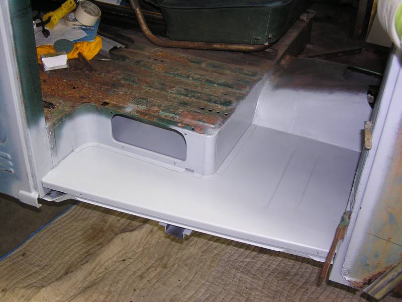
 The seat riser parts are all welded in and the welds ground flush. Have sprayed
a little self etching primer on them for protection. There is no body filler in
any of this yet. That will come later.
The seat riser parts are all welded in and the welds ground flush. Have sprayed
a little self etching primer on them for protection. There is no body filler in
any of this yet. That will come later.
 The last part of the seat riser was made by pressing a form into a sheet of
urethane also.
The last part of the seat riser was made by pressing a form into a sheet of
urethane also.
 The flange was welded on the bottom and we are almost ready to weld in the
replacement piece.
The flange was welded on the bottom and we are almost ready to weld in the
replacement piece.
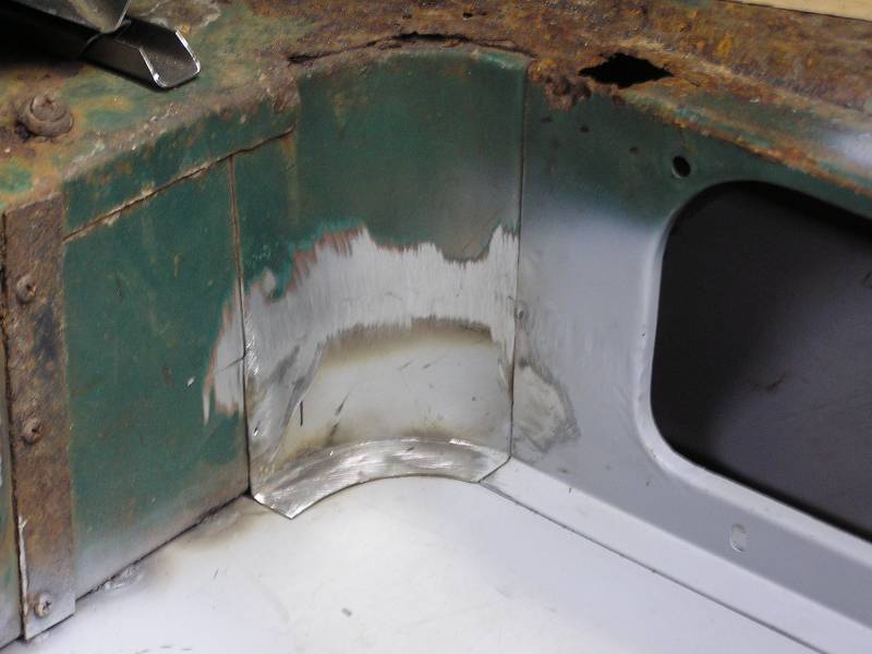 All welded and ground.
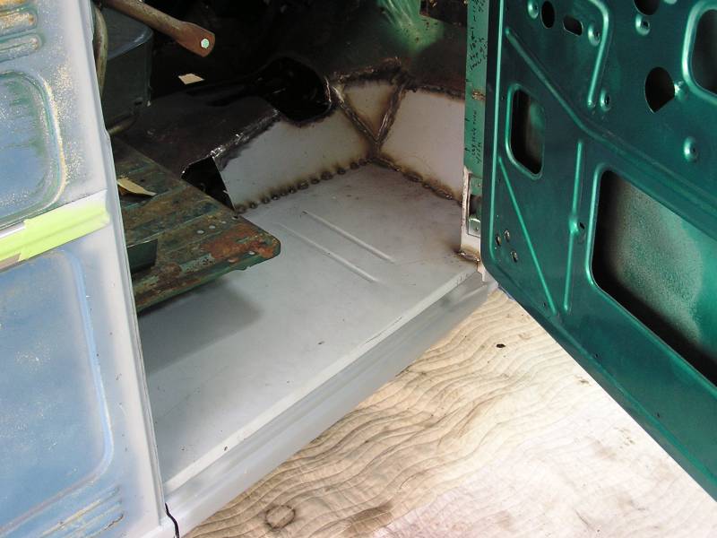
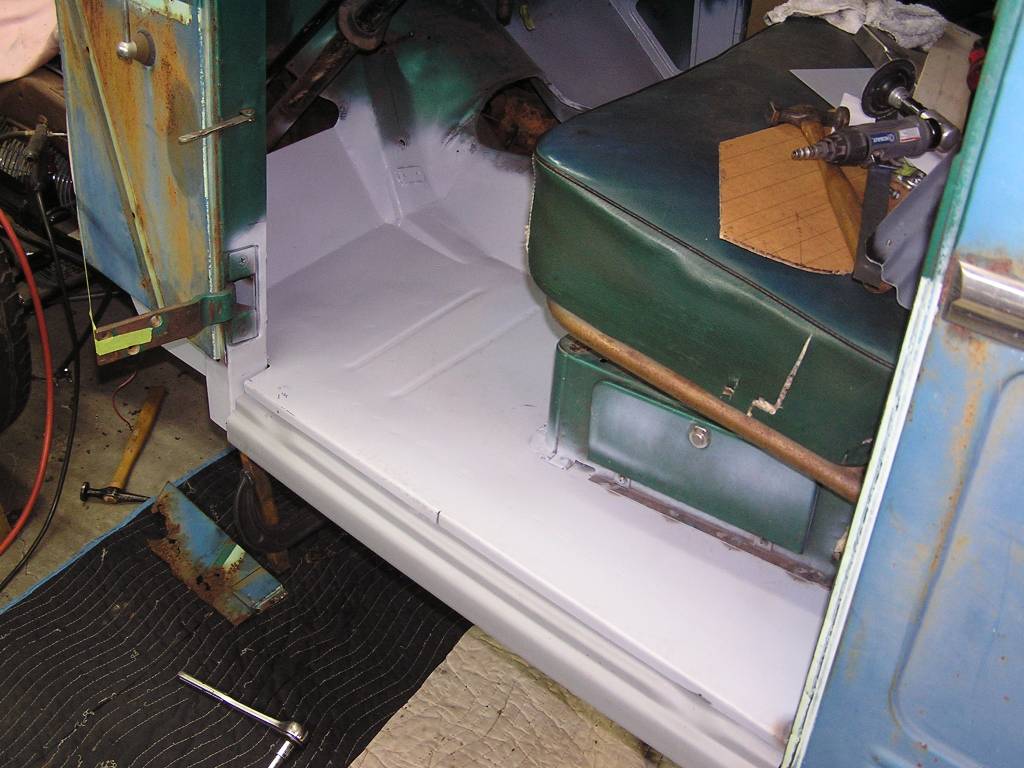
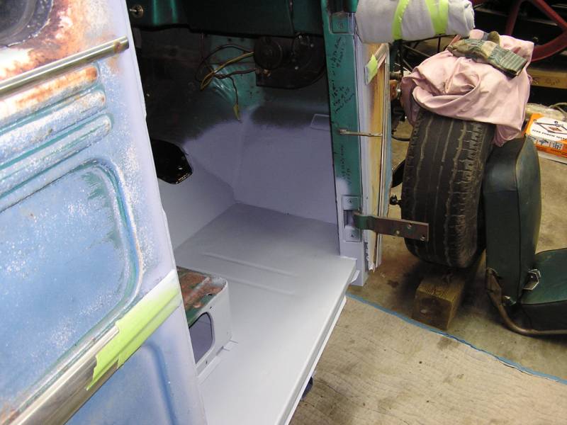 Everything is done on the passenger side floor pan! The welds are ground flush
and primed.
Everything is done on the passenger side floor pan! The welds are ground flush
and primed.
 The back of the floor pan and the seat riser looks great.
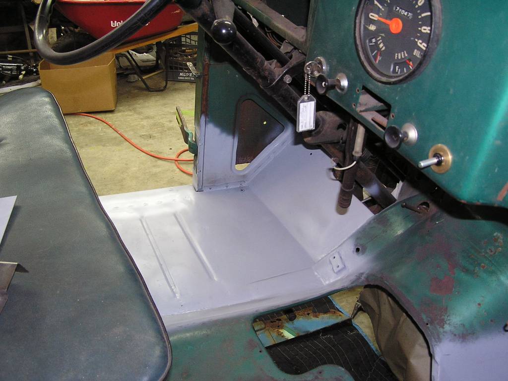
 This is my favorite photo.
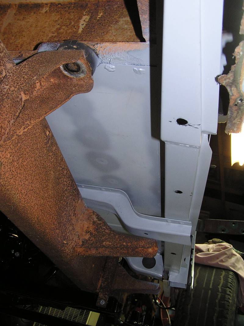 A view underneath showing the floor pan and all the new structural parts all in
place.
A view underneath showing the floor pan and all the new structural parts all in
place.
 This is inboard of the frame rail.
 You can see how high up into the transmission tunnel I had to weld in new metal.
I didn't grind the welds all the way flush for strength reasons, but once
undercoated you'll never see any of this work.
You can see how high up into the transmission tunnel I had to weld in new metal.
I didn't grind the welds all the way flush for strength reasons, but once
undercoated you'll never see any of this work.
Ready to move on to the driver's side.
7/6/09
Driver's side floor pan replacement:
Starting 7/8/09
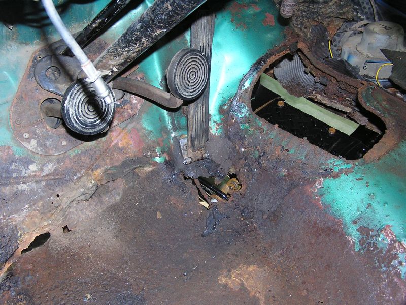
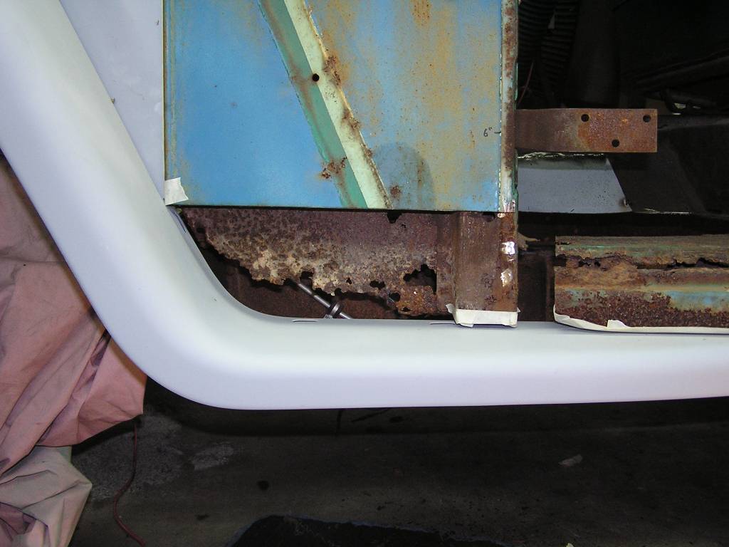
 Rust, rust, rust....goodness. Here are a few photos of what we are dealing with
on the driver's side.
Rust, rust, rust....goodness. Here are a few photos of what we are dealing with
on the driver's side.
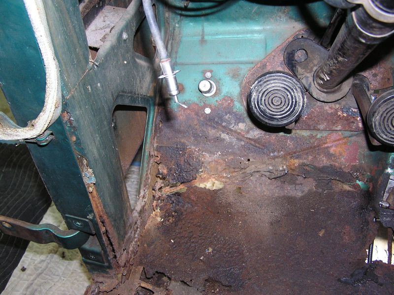
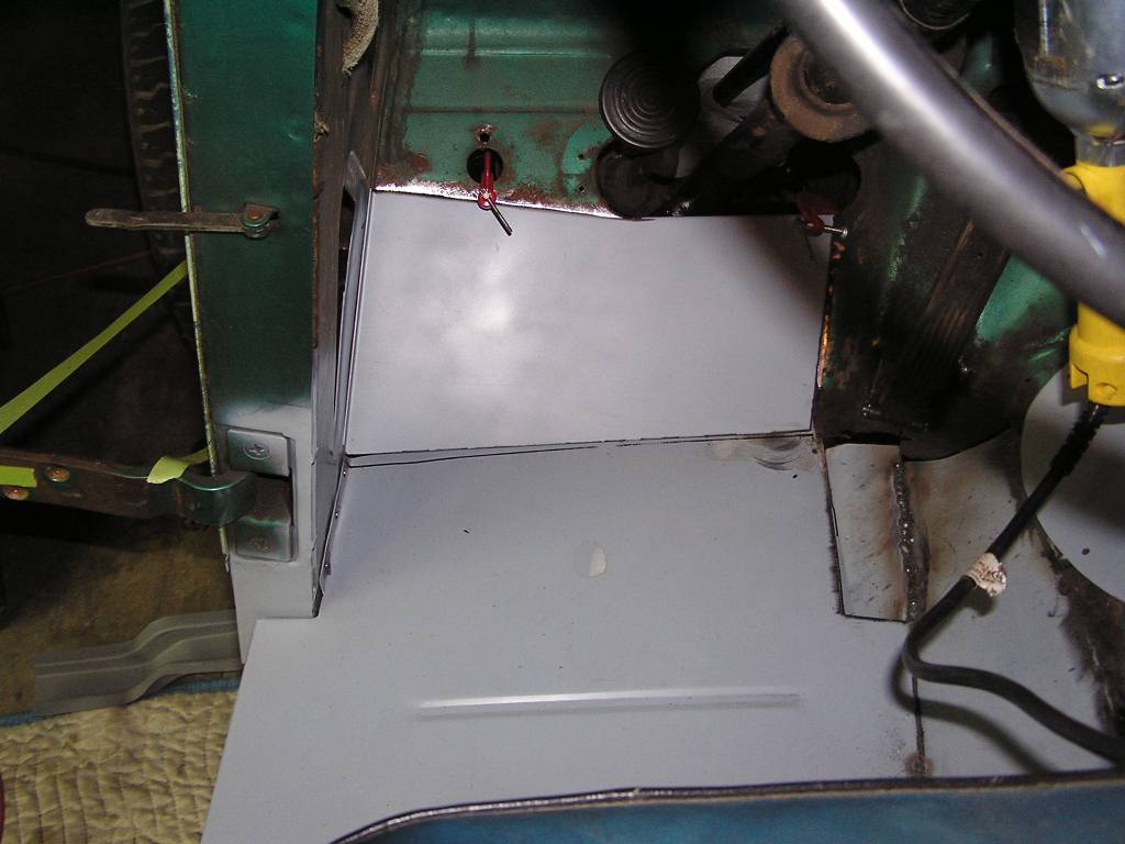
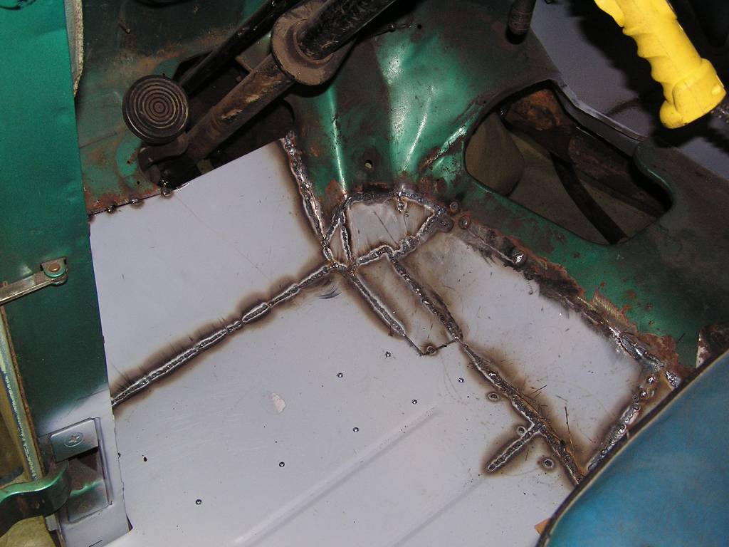
 Directly under the accelerator pedal. Note the cover over the transmission
access has been removed.
Directly under the accelerator pedal. Note the cover over the transmission
access has been removed.
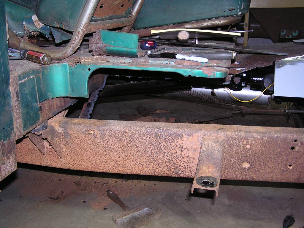
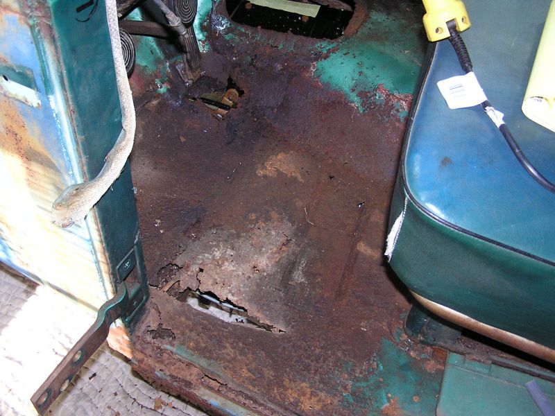 The entire floor pan is dangerously thin. It'll all have to be removed, along
with the structure supports underneath.
The entire floor pan is dangerously thin. It'll all have to be removed, along
with the structure supports underneath.
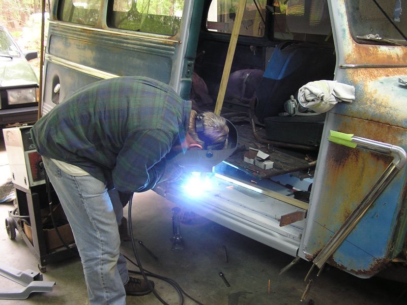
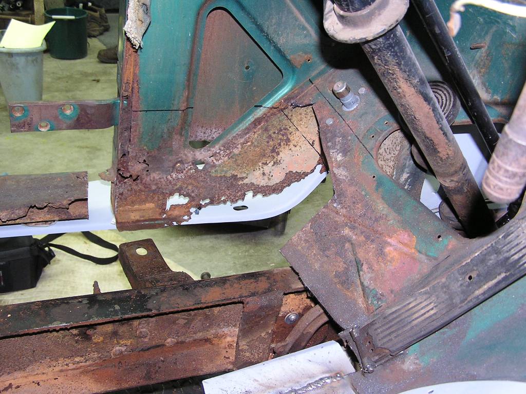
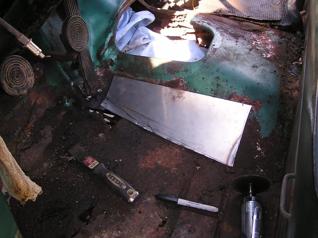 The rust was not limited to just the flat lower portions of the pans, but also
ran up a considerable way into the transmission tunnel. Decided to start with
this area first. The first piece of metal being formed to match the existing
contour.
The rust was not limited to just the flat lower portions of the pans, but also
ran up a considerable way into the transmission tunnel. Decided to start with
this area first. The first piece of metal being formed to match the existing
contour.
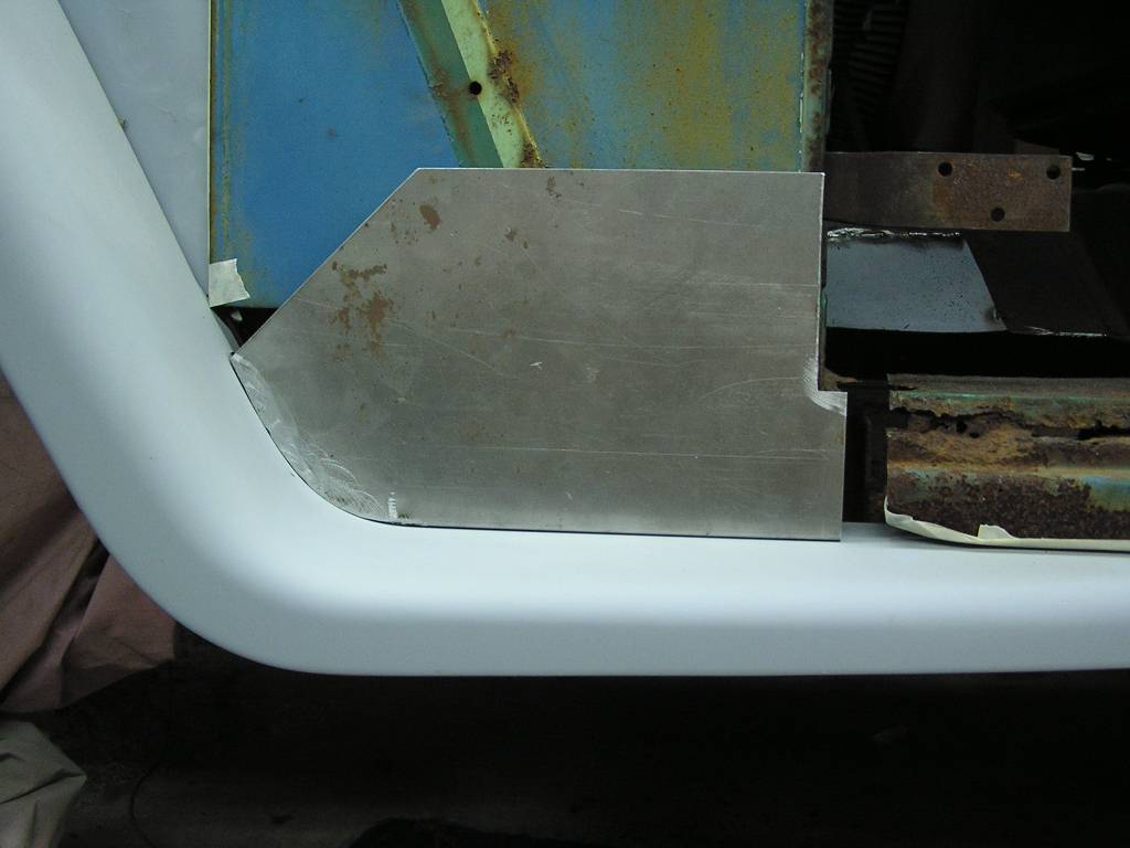
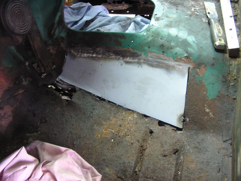 The old rusty metal cut out and the new piece welded in across the top, tying it
in to the original tunnel.
The old rusty metal cut out and the new piece welded in across the top, tying it
in to the original tunnel.
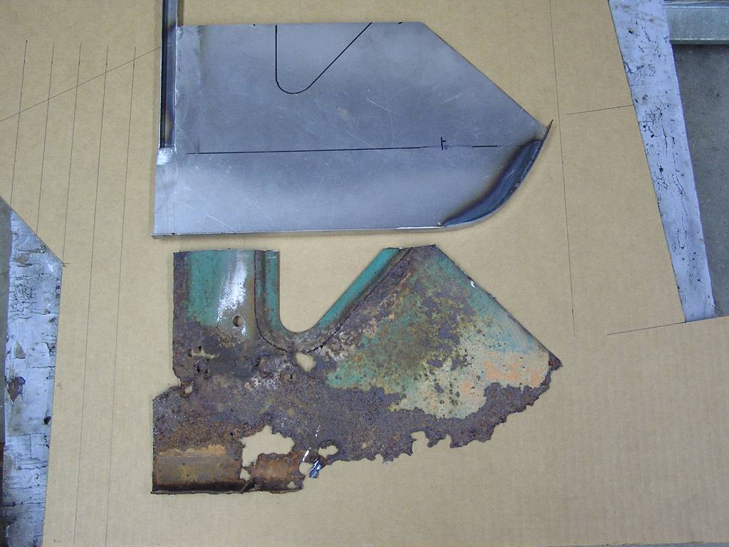
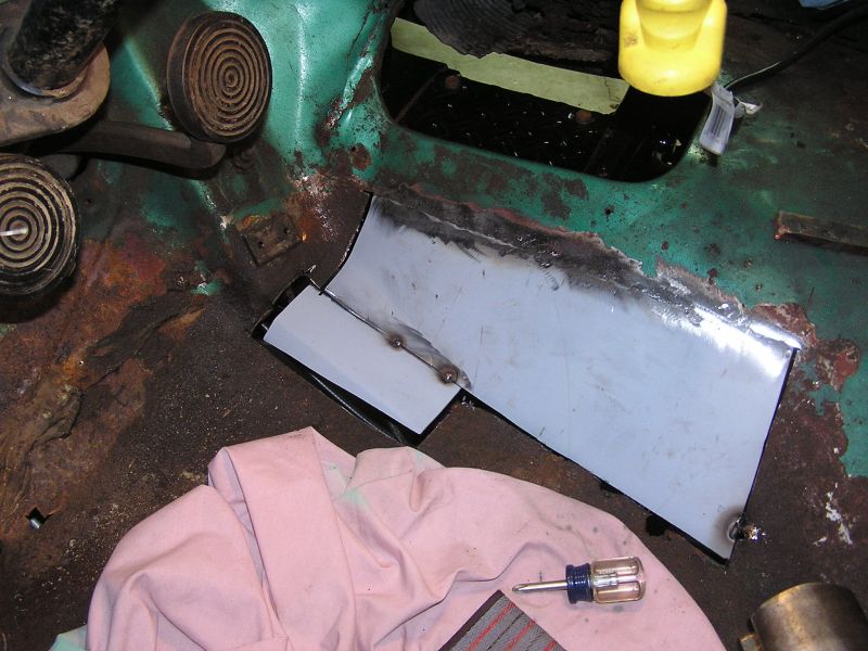 Next is to fab and make the piece that sits right under the drivers right heel.
This completes the transition from the curved tunnel to the flat part of the
floorboard.
Next is to fab and make the piece that sits right under the drivers right heel.
This completes the transition from the curved tunnel to the flat part of the
floorboard.
7/27/09
A good weekend of work. After cutting out most of the driver's floor pan at the front the work on the left inner cowl was begun. First it was decided to fit the left fender to double check the fit of the new inner cowl as we were making it, since there was nothing left of the bottom of the original to follow.
 You can see the badly rusted inner cowl panel. It should follow the basic
profile of the fender and running board.
You can see the badly rusted inner cowl panel. It should follow the basic
profile of the fender and running board.
 And a look at the same from inside the vehicle. Whew!
 Making of the new inner cowl has started. The part has been cut and the 1/2
flange welded all along the bottom that neatly fits the fender contour.
Making of the new inner cowl has started. The part has been cut and the 1/2
flange welded all along the bottom that neatly fits the fender contour.
 The old rusty cowl has been removed. We are going to salvage the coined area
from the old piece and weld it into the new part.
The old rusty cowl has been removed. We are going to salvage the coined area
from the old piece and weld it into the new part.
 All welded, blasted, and primed, ready to weld in. Best part of a full day was
spent on this.
All welded, blasted, and primed, ready to weld in. Best part of a full day was
spent on this.
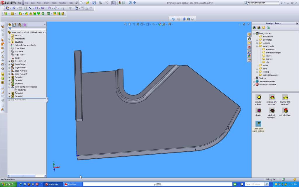 I'm carefully documenting all the work. Using the sheet metal module all parts
are accurately designed in Solid Works. If we decide to do another of these, the
drawings will make the next one much easier.
I'm carefully documenting all the work. Using the sheet metal module all parts
are accurately designed in Solid Works. If we decide to do another of these, the
drawings will make the next one much easier.
7/28/09
 Here the bottom few inches of the front door post are being cut out as it has
gotten rusty and thin in places.
Here the bottom few inches of the front door post are being cut out as it has
gotten rusty and thin in places.
 The old part that was cut out and the new part fabricated to replace it. it is
primed in self etching primer.
The old part that was cut out and the new part fabricated to replace it. it is
primed in self etching primer.
 All welded in, welds ground flush, and touched up with the self etch primer.
7/29/09
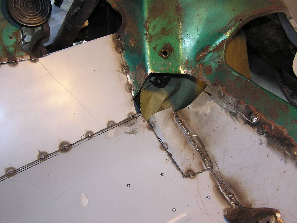
Now that the door post repair is complete it is time to install the inner cowl patch panel.
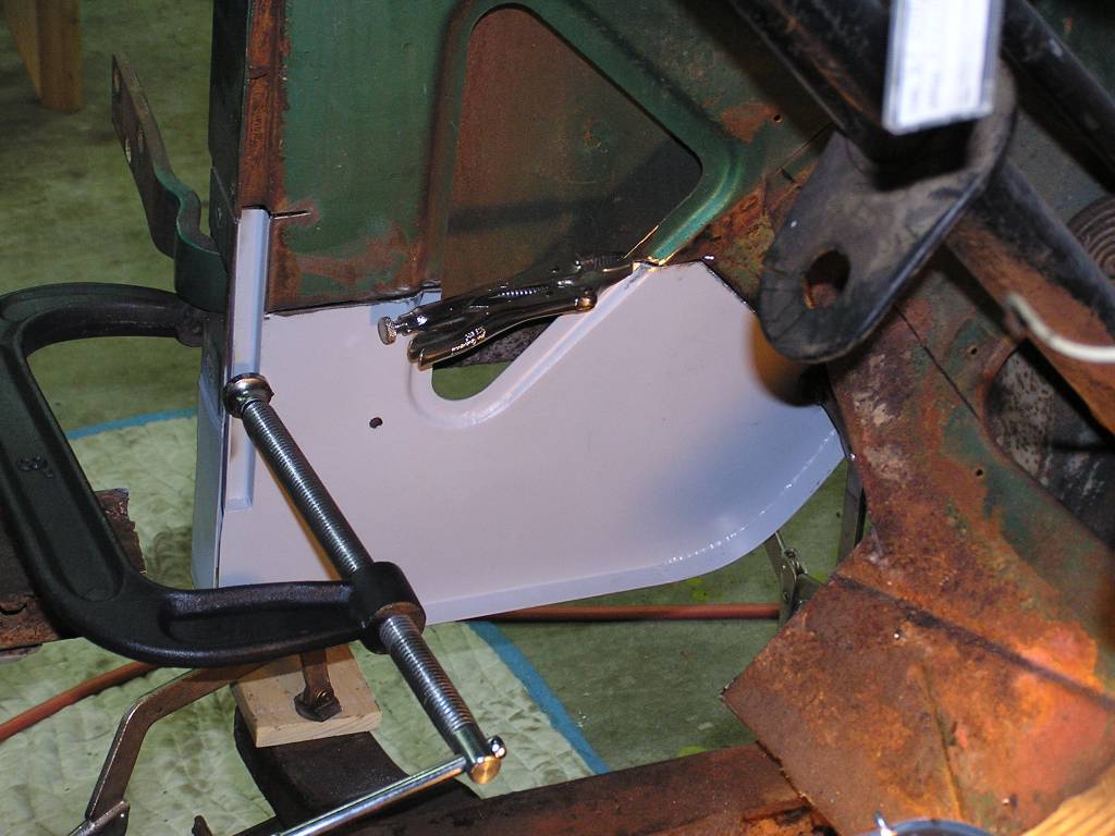 The patch panel is positioned correctly and clamped in place to begin the tack
welds.
The patch panel is positioned correctly and clamped in place to begin the tack
welds.
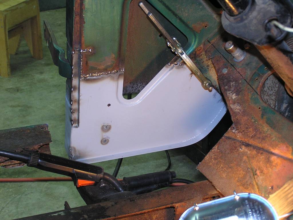 Welding has begun. Not the prettiest weld here, but it has perfect penetration
to the backside of the panel. This is an extremely difficult position to get
into, under the steering wheel laying on your right side. Once the welds are
ground flush, it will look good as new.
Welding has begun. Not the prettiest weld here, but it has perfect penetration
to the backside of the panel. This is an extremely difficult position to get
into, under the steering wheel laying on your right side. Once the welds are
ground flush, it will look good as new.
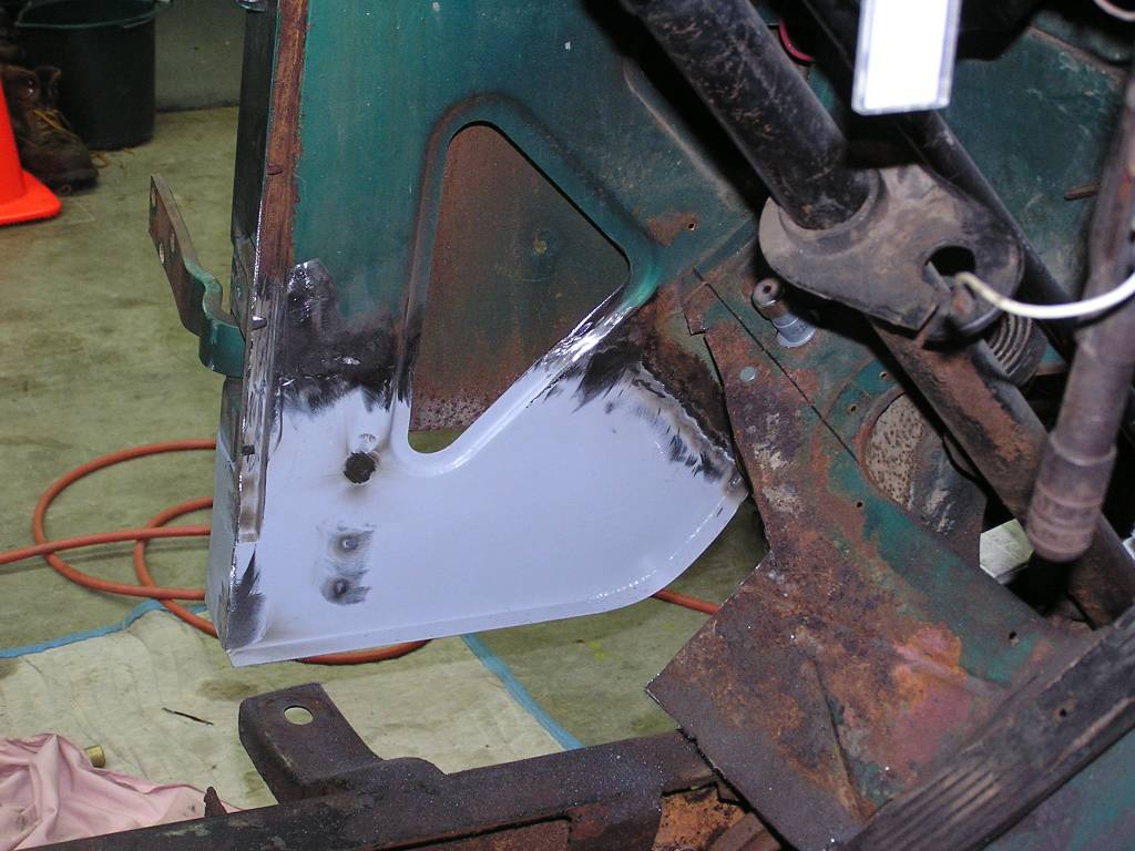 Complete. The welds have been ground
flush ready for primer.
Complete. The welds have been ground
flush ready for primer.
 And a view of the same from the outside.
8/6/09
 Meanwhile, we've been redesigning the stamp dies to make the cowl panel patch
panels. Here is the latest attempt. Looking pretty good!
Meanwhile, we've been redesigning the stamp dies to make the cowl panel patch
panels. Here is the latest attempt. Looking pretty good!
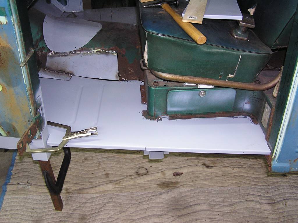
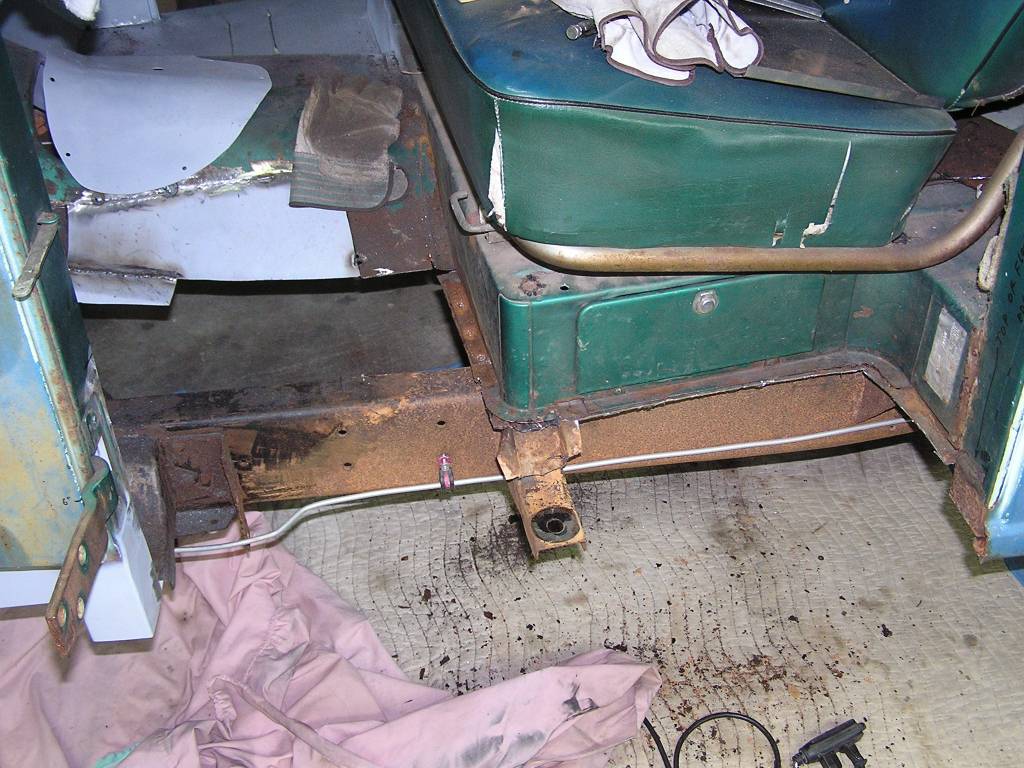 We're working our way aft, removing more and more of the floor pan. Actually
there is very little rust back here, but since we have a full length floor plan,
we're going to use all of it. The seat riser is in much better shape on this
side than the other side was, so it won't have to be cut out. It's a bit of work
cutting all the spot welds loose from underneath. The floor pan under the seat
is almost ready to take out in this photo.
We're working our way aft, removing more and more of the floor pan. Actually
there is very little rust back here, but since we have a full length floor plan,
we're going to use all of it. The seat riser is in much better shape on this
side than the other side was, so it won't have to be cut out. It's a bit of work
cutting all the spot welds loose from underneath. The floor pan under the seat
is almost ready to take out in this photo.
7/10/09
 It was a good weekends work. The last of the old floor pan was removed, the old
welds ground flush, the rust sanded off, and these areas primed in self etching
primer. The balance of the weekend was spent lining up the new floor pan in the
correct location and marking where to trim it to. It was cut out and placed in
position ready to weld in.
It was a good weekends work. The last of the old floor pan was removed, the old
welds ground flush, the rust sanded off, and these areas primed in self etching
primer. The balance of the weekend was spent lining up the new floor pan in the
correct location and marking where to trim it to. It was cut out and placed in
position ready to weld in.
We took about a month off to take summer vacation and to do routine maintenance on a couple of vehicles. The weekend of Sept 12th we were able to devote some time back to the floor pans.
9/14/09
 At the front end of the floor pan, we are starting to fit the replacement piece
for the lower part of the firewall. Made the new panel to line up even with the
opening for the steering column. This will eliminate about 8" of welding.
At the front end of the floor pan, we are starting to fit the replacement piece
for the lower part of the firewall. Made the new panel to line up even with the
opening for the steering column. This will eliminate about 8" of welding.
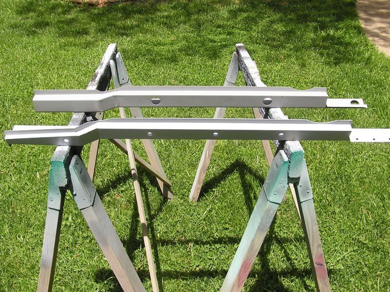
 At the same time the beam that runs under the outboard edge of the floorpan was
prepared. This was made in 2 separate pieces and welded together. I did not like
the commercially available ones as the drop at the back was insufficient to
clear the aft door post.
At the same time the beam that runs under the outboard edge of the floorpan was
prepared. This was made in 2 separate pieces and welded together. I did not like
the commercially available ones as the drop at the back was insufficient to
clear the aft door post.
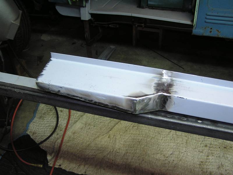 A close up of the aft section of the beam. This drops 3" to fit under the aft
door post properly.
A close up of the aft section of the beam. This drops 3" to fit under the aft
door post properly.
10/5/09
 The front of the floor pan and the lower firewall patch have been tacked
together. This corner, at the driver's right heel, is where the accelerator
pedal mounts. While not rusted thru, it was pitted and thin, so it was cut out.
This would turn out to be a difficult piece to make with the curves and lining
up to all the other surfaces.
The front of the floor pan and the lower firewall patch have been tacked
together. This corner, at the driver's right heel, is where the accelerator
pedal mounts. While not rusted thru, it was pitted and thin, so it was cut out.
This would turn out to be a difficult piece to make with the curves and lining
up to all the other surfaces.
 After much cutting, bending, and fitting, this corner was finally hemmed in. The
welding was all done underneath, because it's a lot easier to grind welds on
outside bends, than from the inside corners. Only a small amount of grinding
will be required on this side to make everything smooth.
After much cutting, bending, and fitting, this corner was finally hemmed in. The
welding was all done underneath, because it's a lot easier to grind welds on
outside bends, than from the inside corners. Only a small amount of grinding
will be required on this side to make everything smooth.
11/19/09
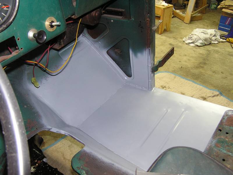
 There have been a lot of distractions over the last month but have finally
managed to wrap up the welding a grinding work on the driver's side floor pan!!!
The corner where the driver's heel rests was a bit of a challenge, but it turned
out well.
There have been a lot of distractions over the last month but have finally
managed to wrap up the welding a grinding work on the driver's side floor pan!!!
The corner where the driver's heel rests was a bit of a challenge, but it turned
out well.
 A view of the outside front portion of the floor pan.
 The final fitting of the driver's door before welding the floor pan to the front
door post. This have to be correct as this supports the front portion of the
rocker panel. The rocker panel needs to line up with the cowl panel and the
bottom edge of the door.
The final fitting of the driver's door before welding the floor pan to the front
door post. This have to be correct as this supports the front portion of the
rocker panel. The rocker panel needs to line up with the cowl panel and the
bottom edge of the door.
Feels good to be done with this portion and we'll soon re-install the exhaust system and transmission. It'll be drivable again.