THE ELUSIVE ROTARY PHASE GENERATOR
by Curt Holland
Much confusion surrounds the technology and equipment sold under brand names like Arco, Rotophase, GWM, Snyder, etc. Once studied a bit, the smoke clears and any competent hobbyist can build his own and save a bundle. The bonus is, that by building your own, you will wind up with a unit that is more precisely matched to your piece of equipment than possible with the "generic" off-the-shelf units. The following is a summary of my experimentations, findings, and eventual reduction to practice of a complete home built single phase to three phase converter that does the tough jobs.
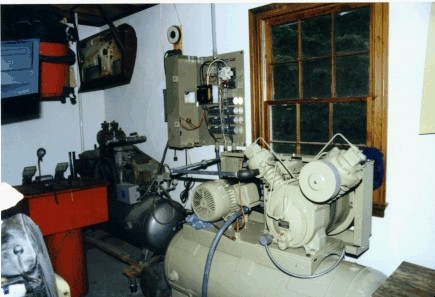
The reason for building a three phase converter was prompted by need for huge amounts of compressed air. Somewhere in the neighborhood of 50CFM at 100PSI was required to run a rather large sandblast cabinet now set up in the garage. Several years ago I purchased a 10 HP Ingersol-Rand two stage compressor intended to supplement an existing 7 HP compressor. I fully intended to bring in the third phase from the power pole behind the house but decided to take a few weeks to fool around with the phase converter.
In the scrap heap at work I found an old 20 HP 3 phase motor of aluminum frame construction. The acids from the chemicals had nearly eaten the cooling fins off. However, checking the windings with a meter showed all three windings to be good with no ground faults. This speaks highly of the quality of TEFC motors.
I began figuring how to get a 3 phase motor to start on single phase power. Once a three phase motor is up to speed it can be singled phased and it runs quite nicely. I finally settled on a big run capacitor. I obtained a 15000 mf @ 600V phase correction capacitor that seems to work just fine as a start capacitor. A much smaller capacitor would do the trick though. The 220v single phase power is applied through a 2 pole switch to the L1 and L2 leads. The start capacitor is attached from the L2 lead to the L3 lead through a momentary switch. If you use a true start capacitor...a word of caution here. Do not leave a start capacitor connected more than a second or two. The absorbed energy will turn it into a small bomb! Been there, done that, etc....
With the 20HP slave motor now starting and running successfully it was time to try starting a heavily loaded 3 phase motor. The next step was to connect a 3 phase switch from the three 20HP motor leads to the three leads on the 10HP air compressor. With the 20HP slave motor running, I flipped the 3 phase switch and voila' the air compressor pulled strongly to full run speed!
However, a few checks with a clamp on ammeter revealed huge imbalances in currents flowing in each of the three phases. The L3 phase (manufactured phase) was pulling almost no current while the L1 and L2 currents were well above nameplate currents. I quickly shut it down to avoid winding damage.
How could the currents be balanced? Well, I remembered about the lead/lag features of capacitors and inductors from the old college electrical engineering classes. With the slave motor and the compressor running once again, I switched in the 15000 mf capacitor (Same one used to start the slave motor). This "excited" the L3 phase resulting in an over-current condition for the L3 and L2 phases. Incidentally, the L1 phase current dropped off dramatically. This pointed to too much capacitance! Turning to the Allied Electronics catalog I placed an order for twelve 50mf @ 440V run capacitors. (Be sure not to substitute start capacitors!) The 440V capacitors are only a dollar more each than the 277V capacitors and the dielectric strength is far superior. This should improve their life span and resistance to spikes, etc.
Once the order arrived it was a process of trial and error to find the right combination of capacitance across the correct phases to get the best current balance. I did discover that, in my application, it was counterproductive to add capacitance across multiple phase groups. They simply counter each other out. In the end I wound up with 350mf across the L2 to L3 leads with single phase power being applied across the L1 and L2 leads on both the slave and compressor motors. This capacitance is applied on the compressor side of the 3 phase switch.
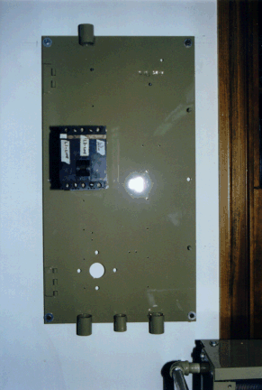
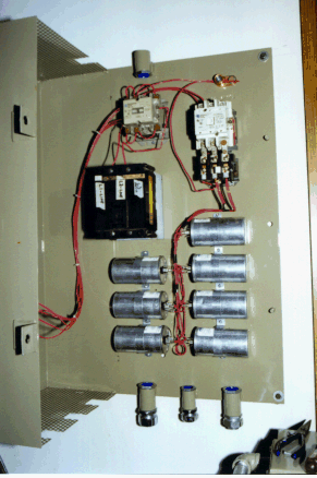
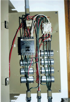
Once every thing was running and well proven the next step was to build a cabinet to safely house the electricals. In the process of building this cabinet I incorporated a few magnetic motor starters and heater blocks to properly protect the windings. The next few pictures are the final electrical wiring schematic and a few photos of the cabinet as it was being built.
If you found this article interesting or need additional information please E-mail me at curt@imc-ma.com
Danny,
Here are a couple of closeups of the wiring at the capacitor lugs. Since the current in the generated leg has to ultimately pass thru the capacitor lugs one has to be sure the wiring can handle this current. For my system the nameplate current was 26 amps per phase. This meant doubling up on a standard wire size like 14ga. This is why you see two wires going to each connector on each lug. I recall calling the capacitor manufacturer and checking on the maximum current each lug could handle. There are 7 capacitors in my system. The 26 amps is divided amongst them because they are in parallel. So 26/7 = 4 amps per capacitor. The slide on terminals must have had more than 4 amps capacity or else I would have used more than one per capacitor lug. It's been running fine for 7+ years now and there is no evidence of any overheating, so my current estimates and wire sizing must have been correct.
 Close up 1 of the lug
connections to the caps: (Click on small thumbnail to see full size image)
Close up 1 of the lug
connections to the caps: (Click on small thumbnail to see full size image)
 Close up 2 of the same.
 Close up of where the
capacitor bank ties into the L2 and L3 legs of the working motor.
Close up of where the
capacitor bank ties into the L2 and L3 legs of the working motor.
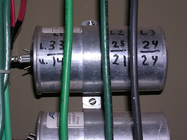 You asked about the
currents. I have this written on one of the capacitors as reference for any
future troubleshooting needs. As follows:
You asked about the
currents. I have this written on one of the capacitors as reference for any
future troubleshooting needs. As follows:
Loaded L1=33, L2=25, L3=24
Unloaded L1=14, L2=21, L3=24
You'll recall single phase power is to L1 and L2, and the generated phase is L3. Capacitance across L2 and L3.
Motor nameplate current is 26 amps. L2 and L3 are under nameplate current for all conditions.
L1 cycles between a slightly overcurrent condition while loaded, and a significantly undercurrent condition for unloaded. My reasoning was that I would overheat the L1 winding slightly while under load and then by passing only 1/2 of the nameplate current while unloaded , the winding would have plenty of time to cool.
Like I've said before I have 7+ years running on it and it continues to work fine. Must have been a good happy balance in the currents.
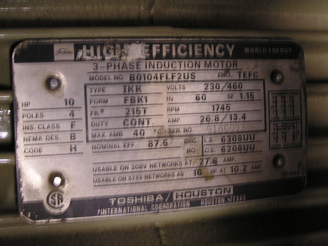 Nameplate showing the 26.8 amps at full load.