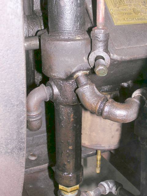
 Here is a picture of an original Stickney fuel pump. After measuring, making a
CAD drawing, and scaling the drawing for shrinkage it was time to prepare a
block of wood.
Here is a picture of an original Stickney fuel pump. After measuring, making a
CAD drawing, and scaling the drawing for shrinkage it was time to prepare a
block of wood. Click on the small images to go to a full size image.
Here is a picture of an original Stickney fuel pump. After measuring, making a
CAD drawing, and scaling the drawing for shrinkage it was time to prepare a
block of wood.
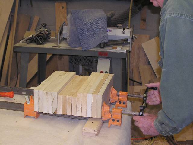 Clayton, a good friend who is also in the cabinet making business, helped me
with the cutting of pieces of wood, gluing, and clamping them together. Cabinet
wood is all 11/16 thick and it takes quite a few pieces stacked together to make
a part of any appreciable size.
Clayton, a good friend who is also in the cabinet making business, helped me
with the cutting of pieces of wood, gluing, and clamping them together. Cabinet
wood is all 11/16 thick and it takes quite a few pieces stacked together to make
a part of any appreciable size.
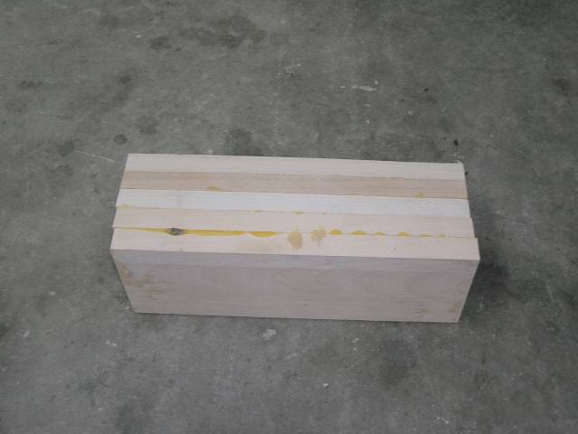 After letting the glue dry for 24 hours we unclamped the parts and this block is
what the fuel pump body will be made from. The wood is Bass wood.
After letting the glue dry for 24 hours we unclamped the parts and this block is
what the fuel pump body will be made from. The wood is Bass wood.
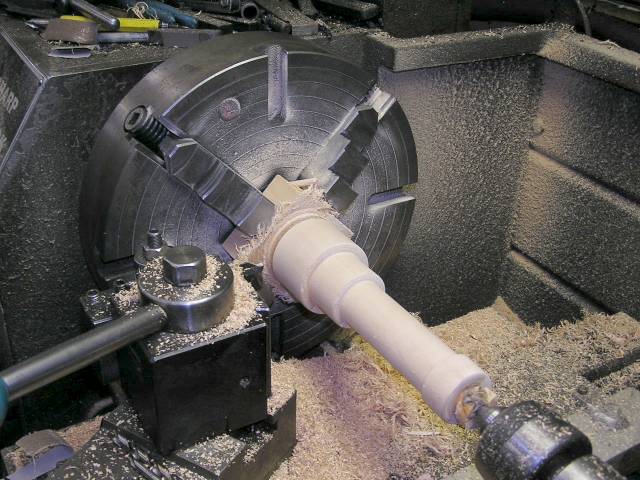
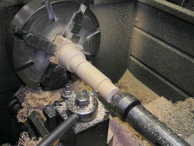 After centering up in a 4 jaw chuck, the square was quickly turned to a round.
Basswood lets you turn 200 thou.
off at a pass! Here the largest diameter has been turned and sanded to final
diameter. I am marking the shoulders for the smaller steps with a standard
parting tool. In fact I just used the parting tool for all the turning too. It
worked as well as any other tool I tried.
After centering up in a 4 jaw chuck, the square was quickly turned to a round.
Basswood lets you turn 200 thou.
off at a pass! Here the largest diameter has been turned and sanded to final
diameter. I am marking the shoulders for the smaller steps with a standard
parting tool. In fact I just used the parting tool for all the turning too. It
worked as well as any other tool I tried.
 The smaller diameters have now been turned and sanded smooth.
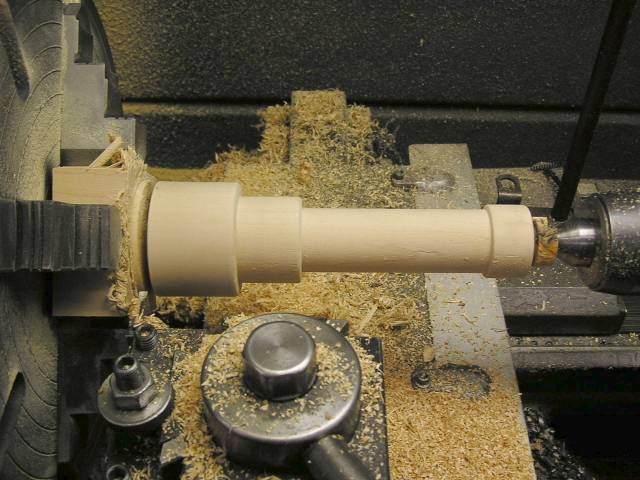 Next to the chuck you can see where the parting tool has been driven in as far
as the tool will allow. All that remains is to do a little sanding while it is
still in the lathe to round the corners and create some draft on the shoulders. Once the sanding is done the tail
stock will be moved away and both ends cut off with a saw.
Next to the chuck you can see where the parting tool has been driven in as far
as the tool will allow. All that remains is to do a little sanding while it is
still in the lathe to round the corners and create some draft on the shoulders. Once the sanding is done the tail
stock will be moved away and both ends cut off with a saw.
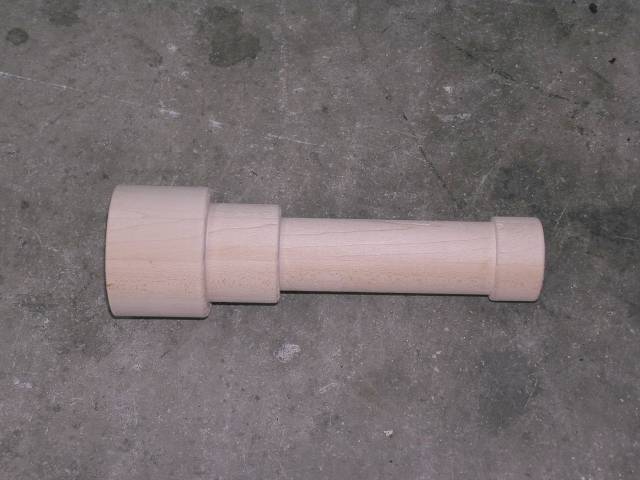 The lathe work is complete. I will just use body
filler instead of leather fillet material to create the blended radii.
The lathe work is complete. I will just use body
filler instead of leather fillet material to create the blended radii.
Unfortunately I lost several pictures in a hard drive crash that documented the pieces that get added next to this fuel pump body. The fuel inlet and outlet bosses and the mounting bracket were added next. The completed pump body can be seen sitting on the parting board next.
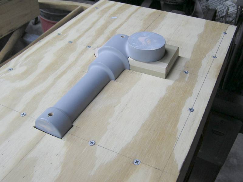
 Now that most of the pattern is complete it is time to make the follow board for
this loose pattern. This needs to be done to aid ramming the drag and also to establish the thickness of the core
print. You can see the
scribe lines showing part midline.
Now that most of the pattern is complete it is time to make the follow board for
this loose pattern. This needs to be done to aid ramming the drag and also to establish the thickness of the core
print. You can see the
scribe lines showing part midline.
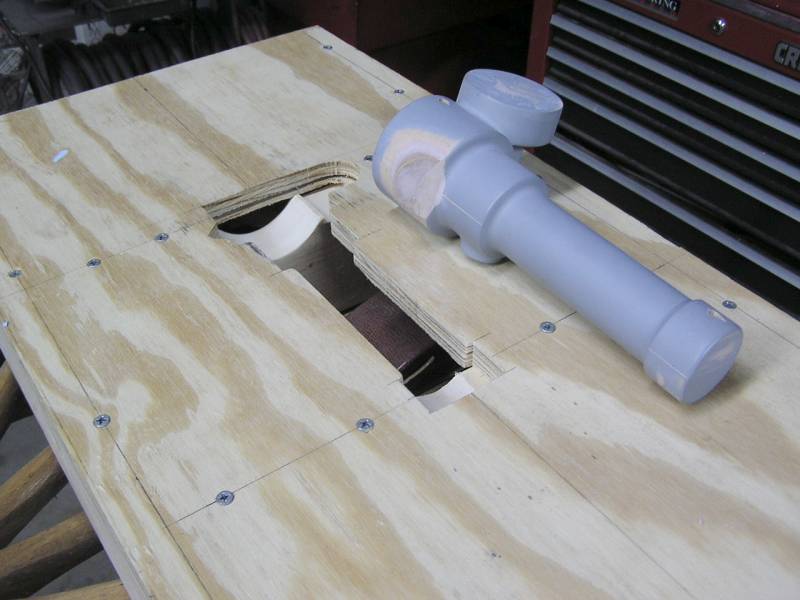
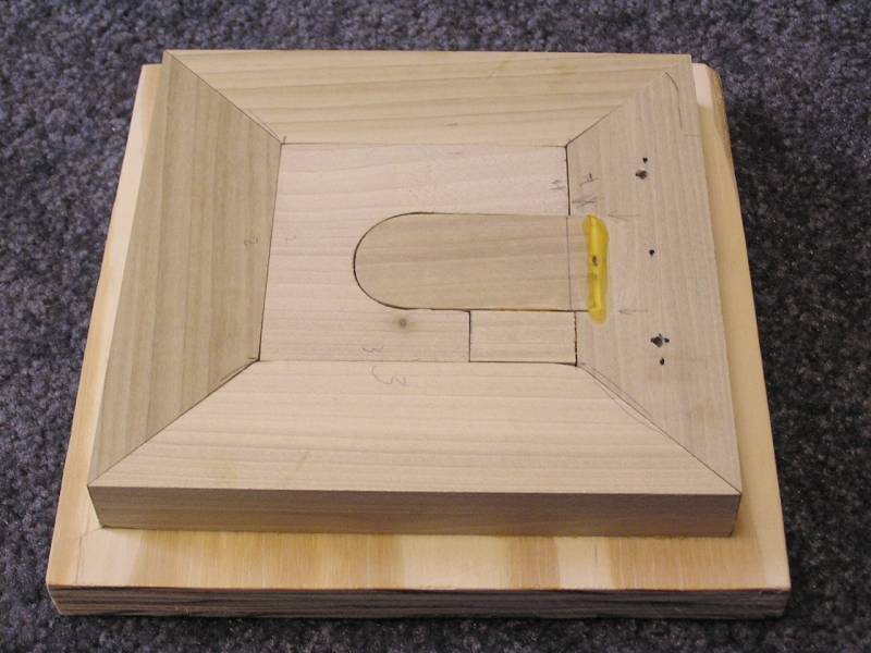
 Here the finished pattern has been set in the follow board exactly on
centerline. However, there is a big problem! If you were to ram the drag like
this, flip it over, remove the follow board and then try to remove the pattern
the mold would be ruined. Green sand would have been rammed under this flange
preventing the part from being removed.
Here the finished pattern has been set in the follow board exactly on
centerline. However, there is a big problem! If you were to ram the drag like
this, flip it over, remove the follow board and then try to remove the pattern
the mold would be ruined. Green sand would have been rammed under this flange
preventing the part from being removed.
 View of the same problem area on the other side. The only solution is to make a
core print and core box to create a no bake core that will form this part of the
mold. This was the most difficult part of the project for me to understand. I
had several conversations with a local foundry and a good friend who is a
pattern maker before it finally sank it. Guess I'm a little slow....
View of the same problem area on the other side. The only solution is to make a
core print and core box to create a no bake core that will form this part of the
mold. This was the most difficult part of the project for me to understand. I
had several conversations with a local foundry and a good friend who is a
pattern maker before it finally sank it. Guess I'm a little slow....
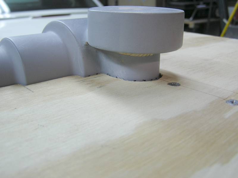
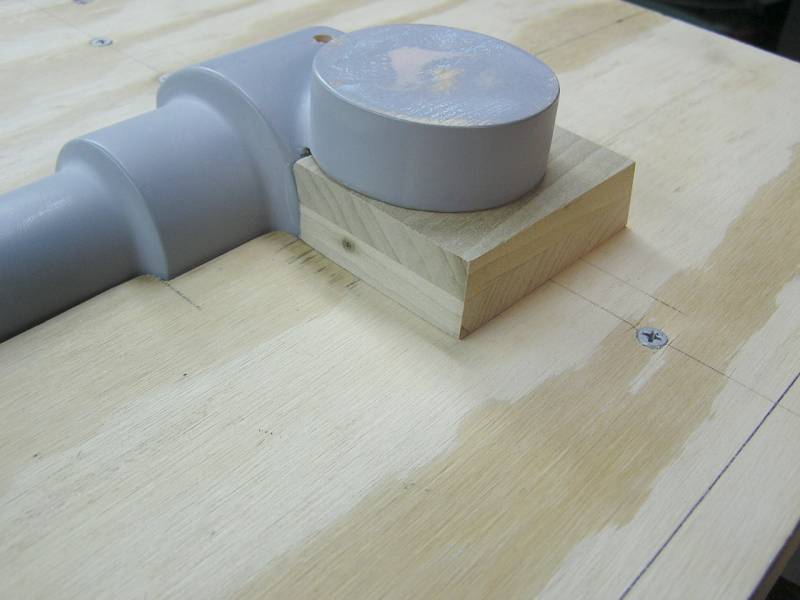
 The piece of wood under the
large round boss is the beginning of the core print that will form the fuel pump
body
between the lower edge of the round boss and the follow board.
The piece of wood under the
large round boss is the beginning of the core print that will form the fuel pump
body
between the lower edge of the round boss and the follow board.
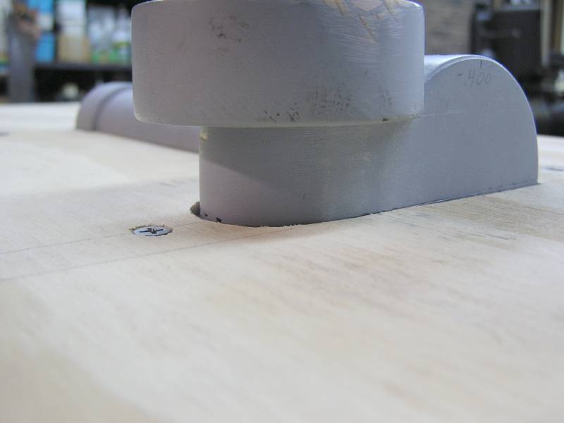
 And a close up of the same. It's hard to tell but the outer edges of the core
have a 5° draft to assure easy removal from the drag mold and from the
core box. The draft has to be in the correct direction to serve both molding
operations.
And a close up of the same. It's hard to tell but the outer edges of the core
have a 5° draft to assure easy removal from the drag mold and from the
core box. The draft has to be in the correct direction to serve both molding
operations.
 The core print removed so the inside detail can be seen.
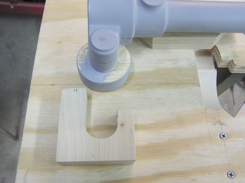
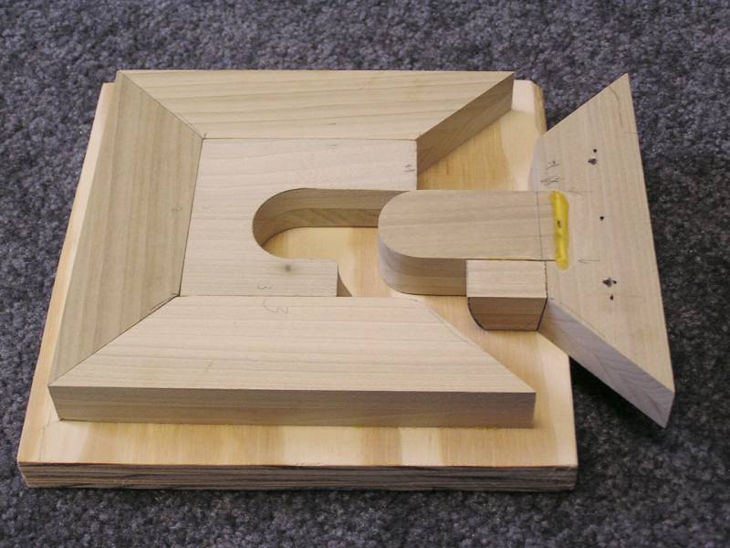
 Once the core print is accurately made to fit the pattern, the core box can be
built around the core print. Basically a picture frame was built around the core
print fitting tight to it. There is no substitute for a good accurate power
miter saw here! Luckily I had one from doing all the trim work in the house
restoration.
Once the core print is accurately made to fit the pattern, the core box can be
built around the core print. Basically a picture frame was built around the core
print fitting tight to it. There is no substitute for a good accurate power
miter saw here! Luckily I had one from doing all the trim work in the house
restoration.
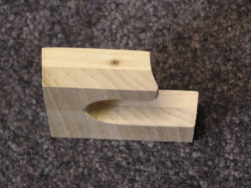 Here is the core print again. You can see the 5° draft on the outer edges pretty
good in this view. The core would come up out of the core mold pretty good,
except for the negative draft problem on the front edge. This sweeping radius
forms a portion of the round pump body and creates a problem in the core
box.
Here is the core print again. You can see the 5° draft on the outer edges pretty
good in this view. The core would come up out of the core mold pretty good,
except for the negative draft problem on the front edge. This sweeping radius
forms a portion of the round pump body and creates a problem in the core
box.
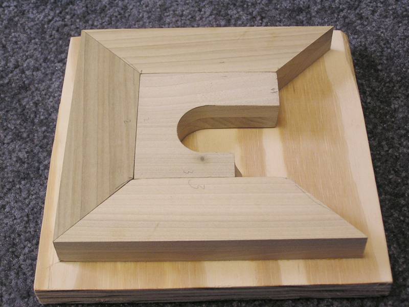 Again the core print in the core box. You can just see the problem area and how
it would prevent the core from coming out of the mold here.
Again the core print in the core box. You can just see the problem area and how
it would prevent the core from coming out of the mold here.
 The only solution is to make a portion of the core box removable to allow the
core to be removed.
The only solution is to make a portion of the core box removable to allow the
core to be removed.
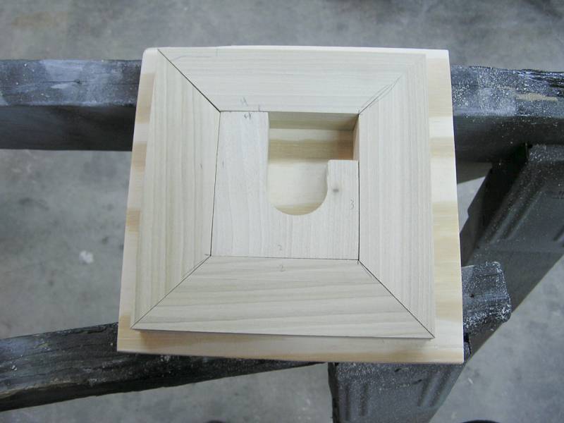
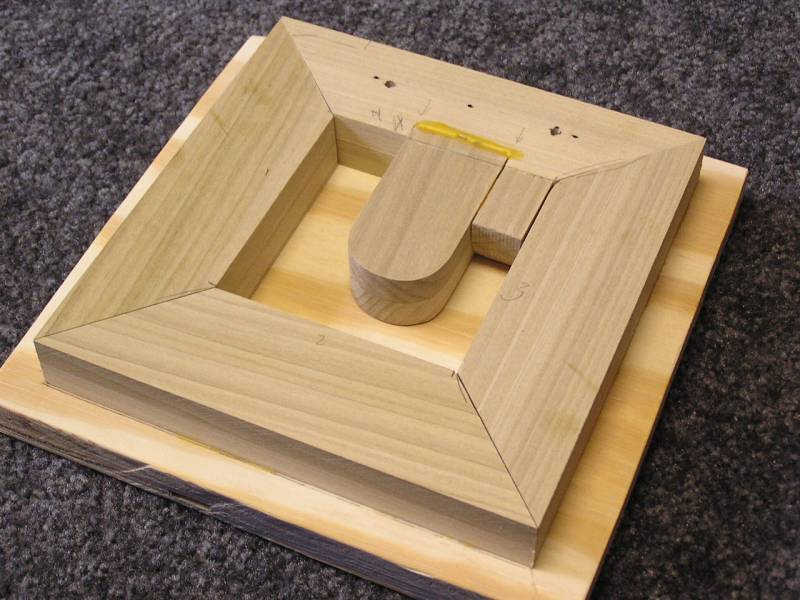
 Here is the complete core box with the core print inside. For casting accuracy
there needs to be a good match between the core box and the print.
Here is the complete core box with the core print inside. For casting accuracy
there needs to be a good match between the core box and the print.
 With the core print removed the core box is complete. This is the finished box
that will be used to make the no bake core.
With the core print removed the core box is complete. This is the finished box
that will be used to make the no bake core.
 To wrap things up the core print needs to be glued to the pump
pattern.
To wrap things up the core print needs to be glued to the pump
pattern.
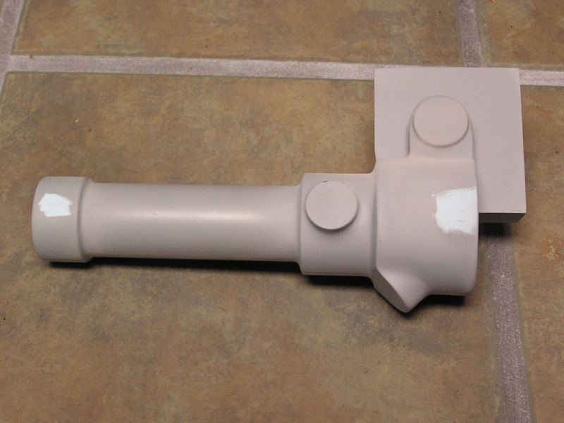
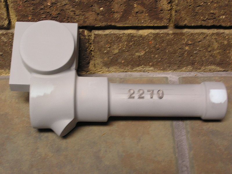 The final priming and finishing work has been done and the part
numbers added. Stickney put the part number on the back side of the fuel pump
where they can't be seen when it is installed. So that's why I did it too.
The final priming and finishing work has been done and the part
numbers added. Stickney put the part number on the back side of the fuel pump
where they can't be seen when it is installed. So that's why I did it too.