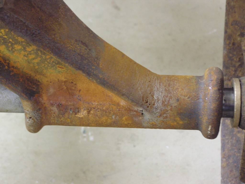
A small engine cart was picked up in Baraboo, WI a couple of years ago. It was a collection of bits made to roll and that was about it. It needed some serious help! The steel axles in main bolter castings were nearly rusted in two and were cast in place, making their removal quite difficult. One casting end didn't survive and needed to be welded. Cast iron rod and boric acid flux were used to gas torch weld the pieces back together. The weld was ground flush and other than a few gas holes, you can't tell anything was ever done to this. It's all rusting back quite nicely too as I've left the part out in the rain a few times to try and restore the original patina. Very pleased how this turned out.
You can just see the new Oilite bushing pressed in the wheel hub. The wheels were set up in a large lathe and bored to 1-3/8" and fitted with the Oilite bushings. This is a nice fit on the new TG&P axles.
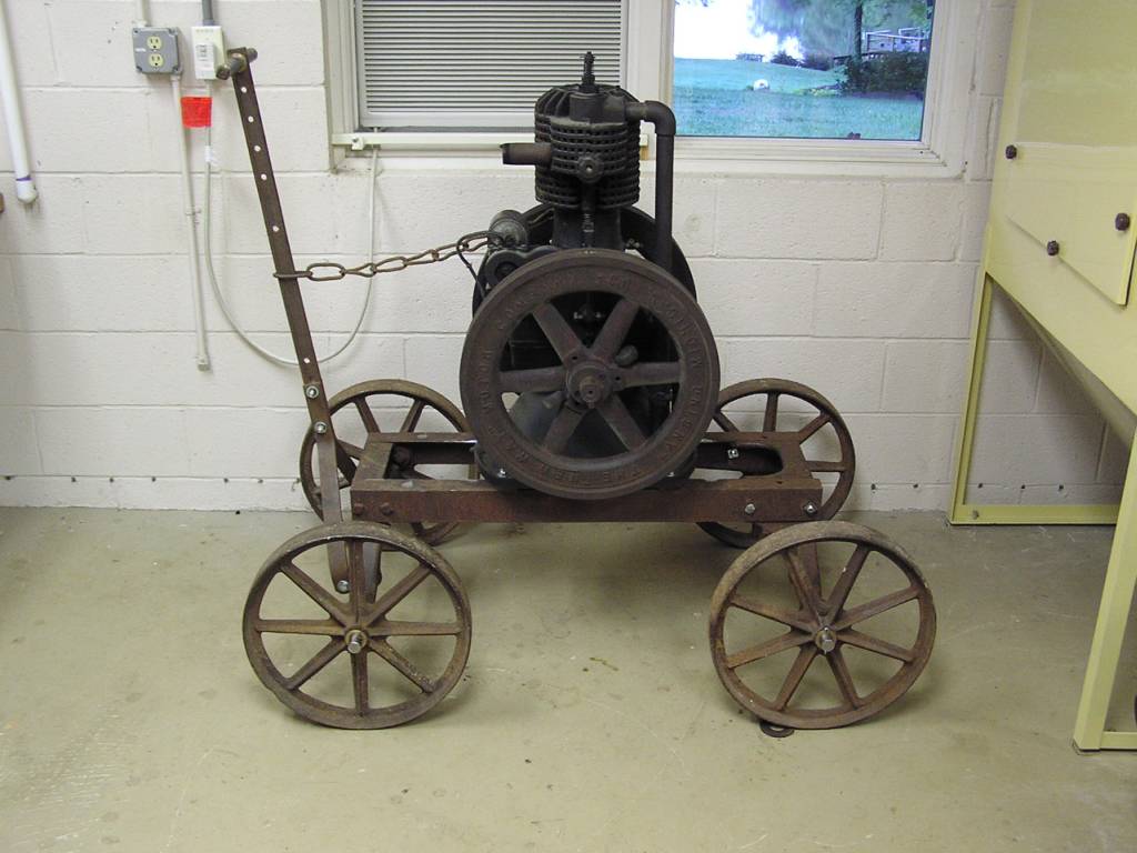
The cart all reassembled. I think the wheels are IHC and the cart is Galloway. Yes it's a collection of various pieces thru the ages, but that's the appeal of this cart. The chain holding the cart handle is all hand forged by some blacksmith eons ago.
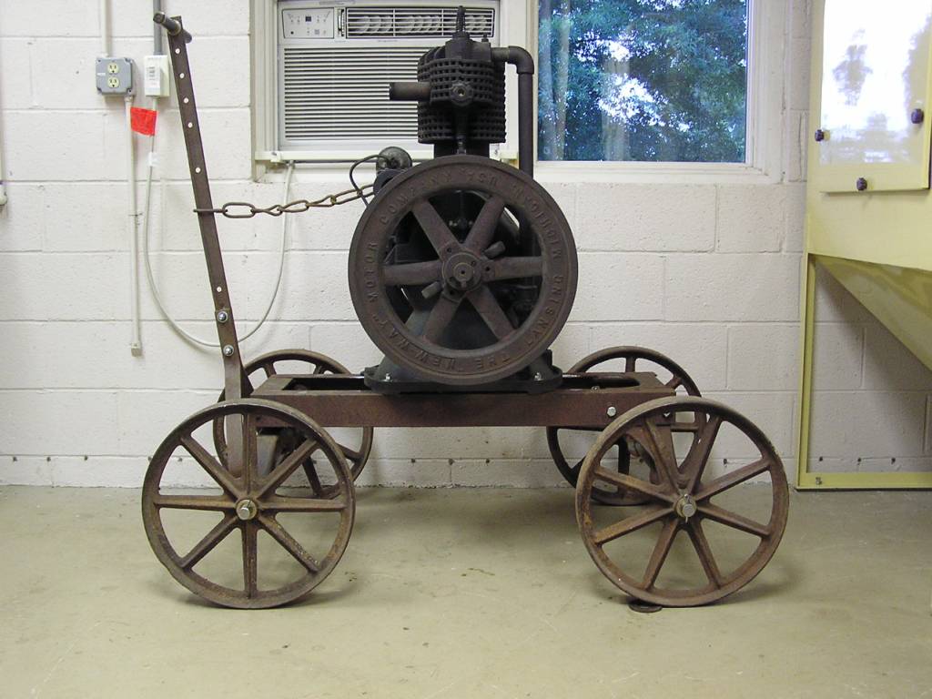
The proportions of the engine to the cart are just right. really pleased how it turn out.
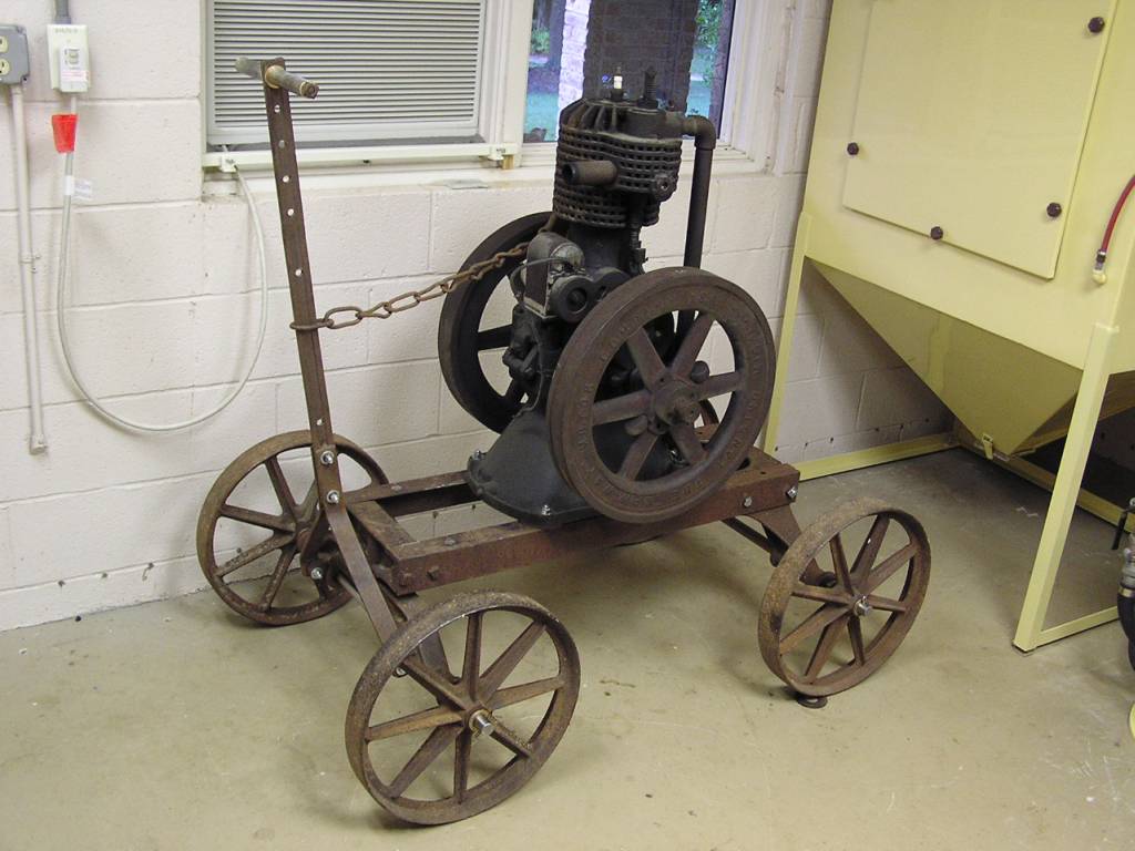
Missy even wanted to keep the old pieces of 1/2" galvanized pipe that make the handle. These were trued on the ends to make square and little brass bushings turned in the lathe to make the pipe pieces center on the draw bolt.
Now to get the engine running.....
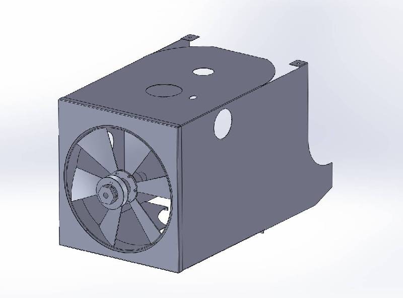
Solid Works 3D layouts done of the missing parts.
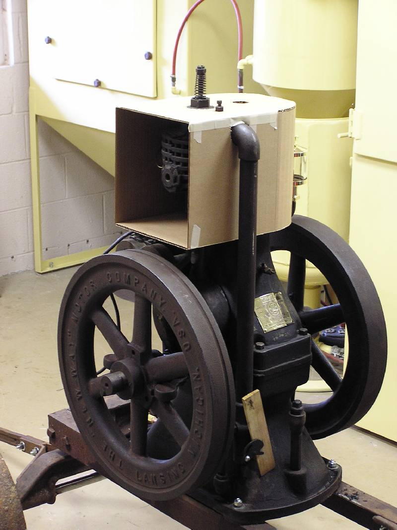
Since all of the sheet metal that routes cooling air thru the engine fins was missing, layouts began to make replacement sheet metal. 3D SolidWorks layouts were drawn, plotted to scale and cutout in cardboard to check fit. Several rounds of this, like 5 of them, were made and finally a dxf file was sent to the laser burnout machine and the profiles were cut. This was folded on the bend lines and the parts were ready.
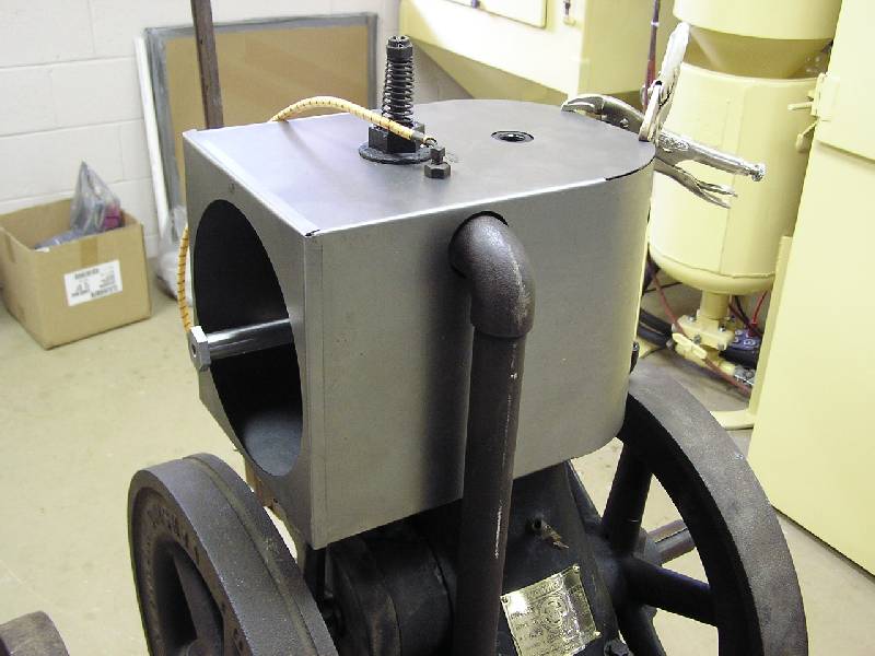
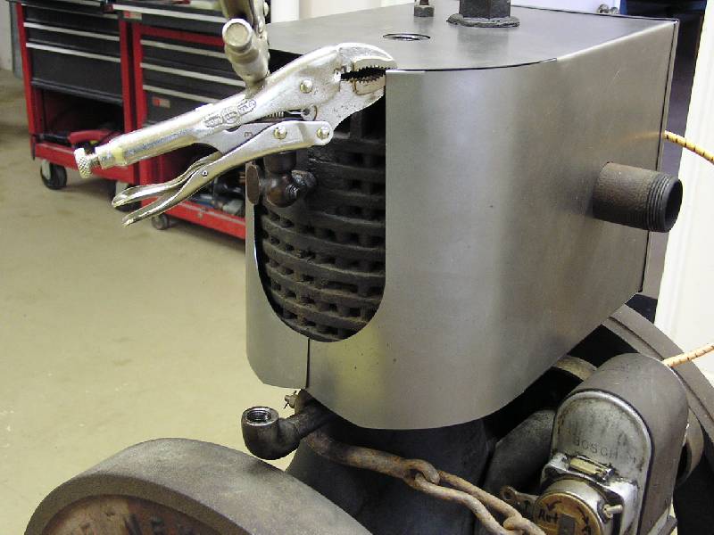
Here the new sheet metal is being fitted for the first time. The ends were hand rolled by working over a piece of 6" and then 4" tubing. Turned out pretty decent I think. The original sheet metal was only .015 thick. I made these from .025 thick steel, so hopefully it will be a little more durable than the originals.
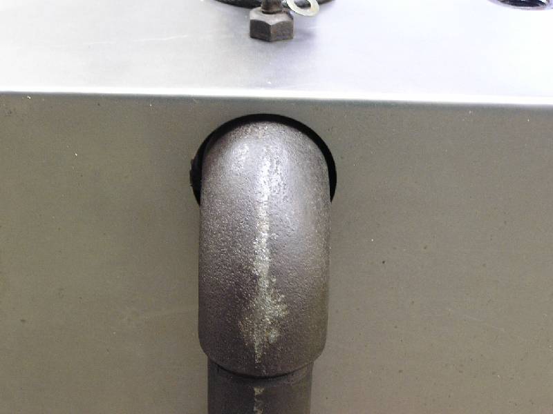
Close up of good fit around intake pipe.
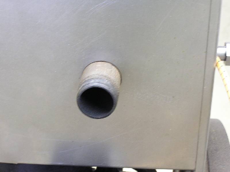
And similar good fit around exhaust pipe.
A view of the exit end of the cooling air.
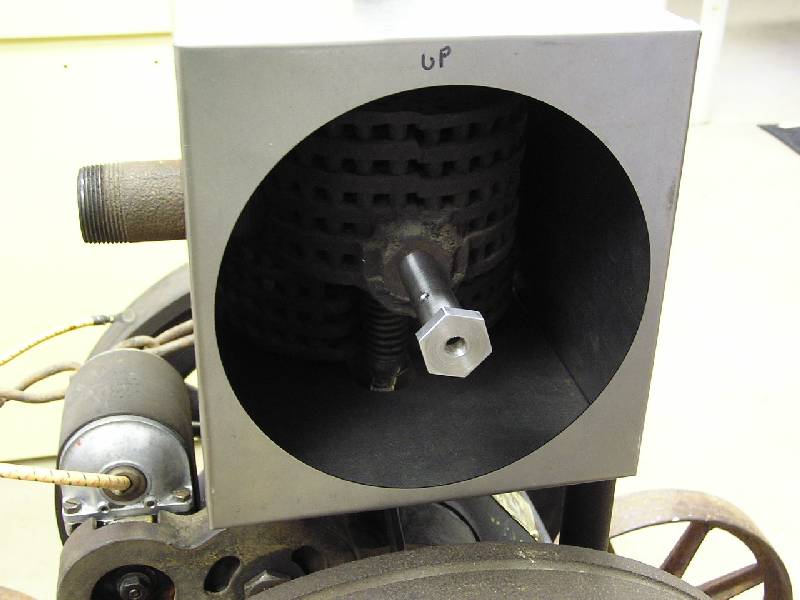
The stub shaft the fan assy will turn on was made on Saturday 7/21/12. It screwed right in place.
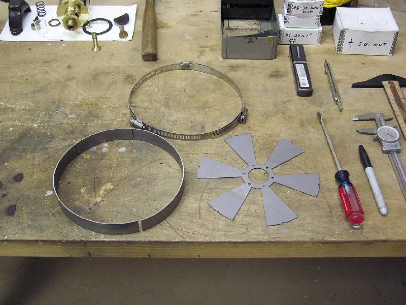
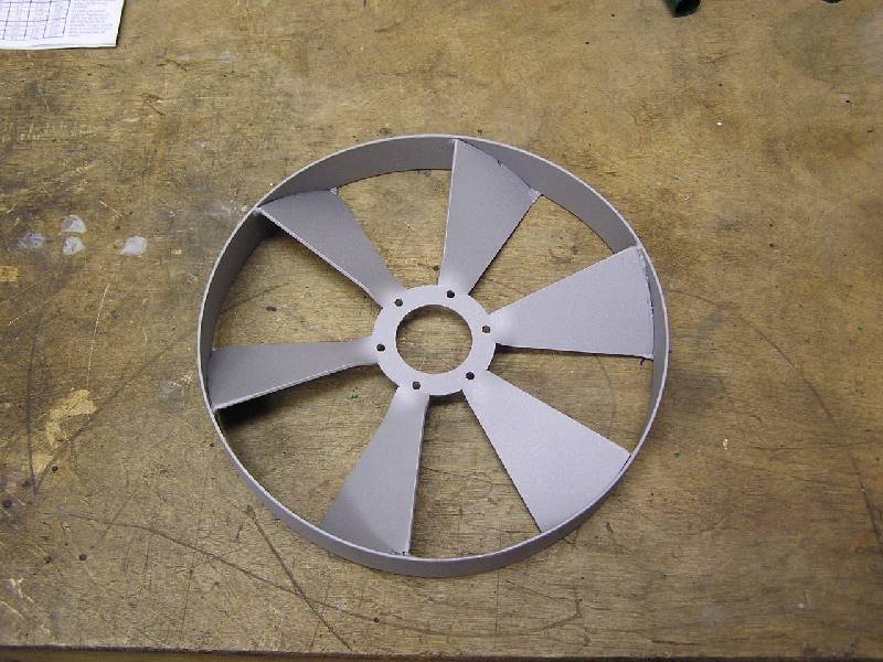
Here is the flat laser burnout of the fan blade, along with a rolled ring that is 1" wide. The worm gear clamp will be used draw the ring closed around the fan blade.
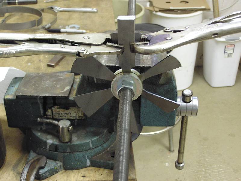
Some simple tooling was made to aid bending each blade the same way.
This is the side of the fan blade facing out. All the welding was done on the far side, facing the engine. The little fan blades on New Ways took a beating and it's nearly impossible to find an original, since they were so delicate. I made all the parts from 18 ga (.049) so hopefully this one will last many years.
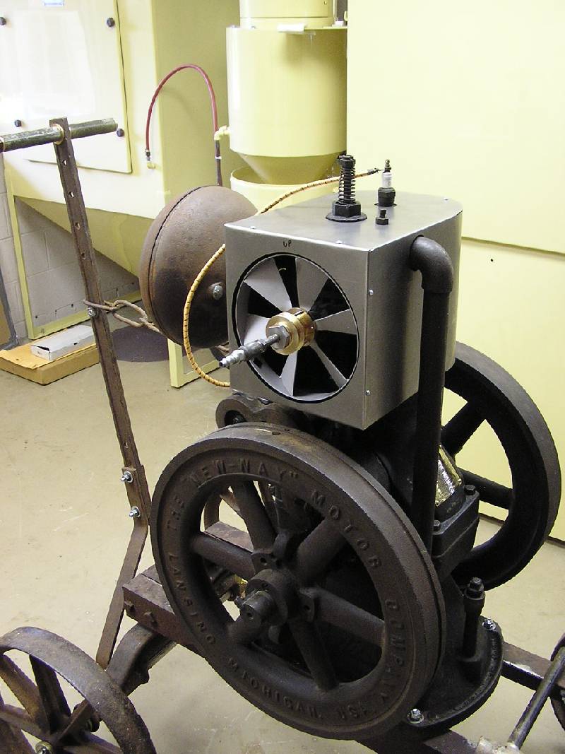
Fan blade assy added to the shroud.
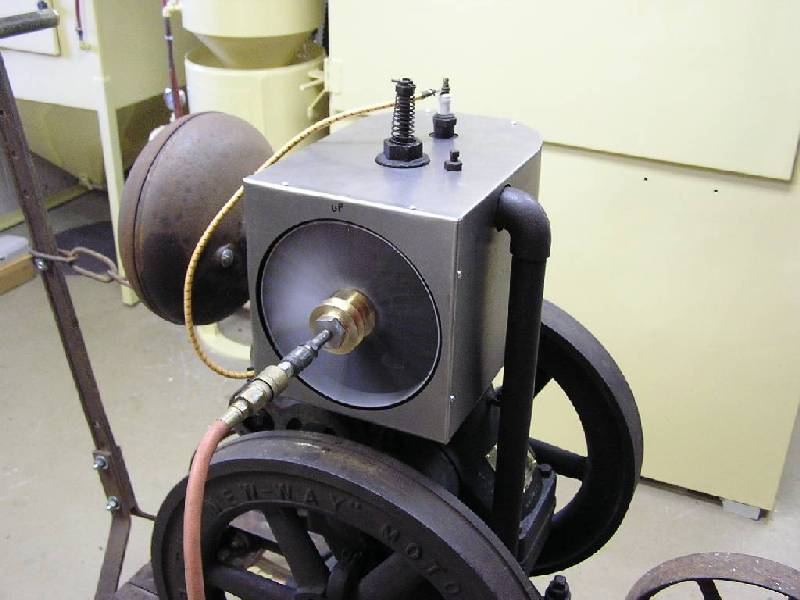
Since the little fan blade turns so fast, I decided to attempt balancing it. Very light oil was applied to the shaft and fan. Low air pressure was blown in the lube port to "float" the blade, much like air hockey. The blade would spin and spin and spin and eventually rock back and forth leaving the heavy spot at the bottom. It only took 3 small squares of magnetic sign material to balance, so the fan was nearly perfectly balanced as it was made.
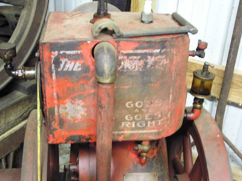
Meanwhile I had a look at Tommy's New Way to see what the original graphics looks like. Anyone know where some graphics files could be obtained? A template to aid spraying the graphics would certainly be nice.