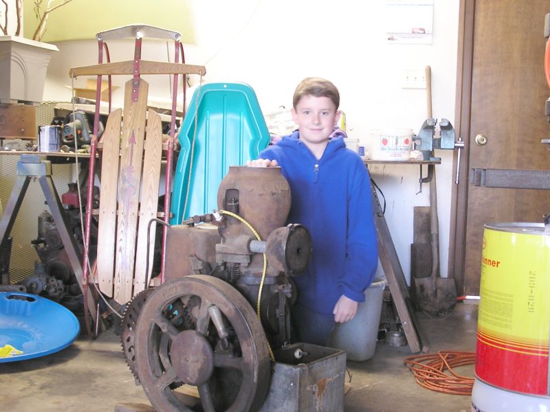
 At Portland '03 Devin picked out his first engine, a nice Baker Monitor. Within
a few hours after getting it back to the list area the group had it running.
At Portland '03 Devin picked out his first engine, a nice Baker Monitor. Within
a few hours after getting it back to the list area the group had it running. Click on the small thumbnails to see a larger image.
At Portland '03 Devin picked out his first engine, a nice Baker Monitor. Within
a few hours after getting it back to the list area the group had it running.
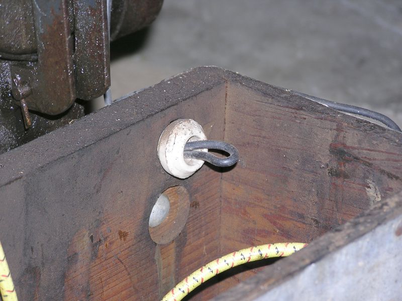 The little ceramic insulators were still in the battery box!
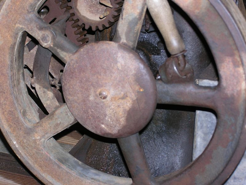 The original hopper lid attached to the crankshaft. Very rare to find one in
place!
The original hopper lid attached to the crankshaft. Very rare to find one in
place!
 And
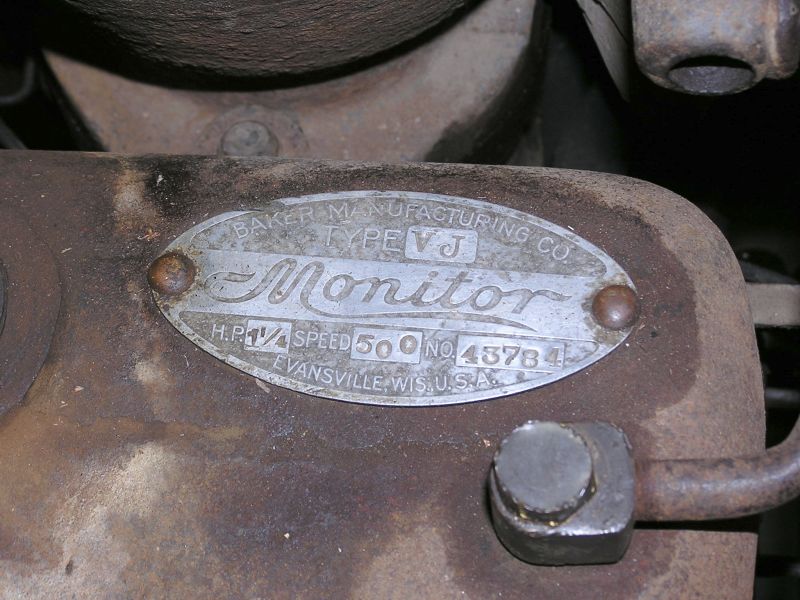
the ID tag showing the s/n of 43784.
And
the ID tag showing the s/n of 43784.
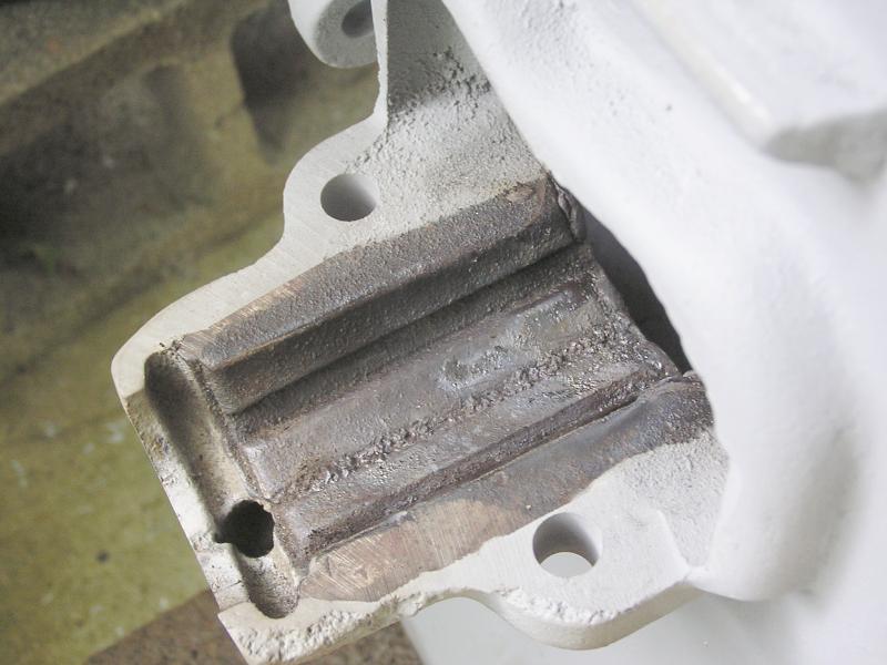
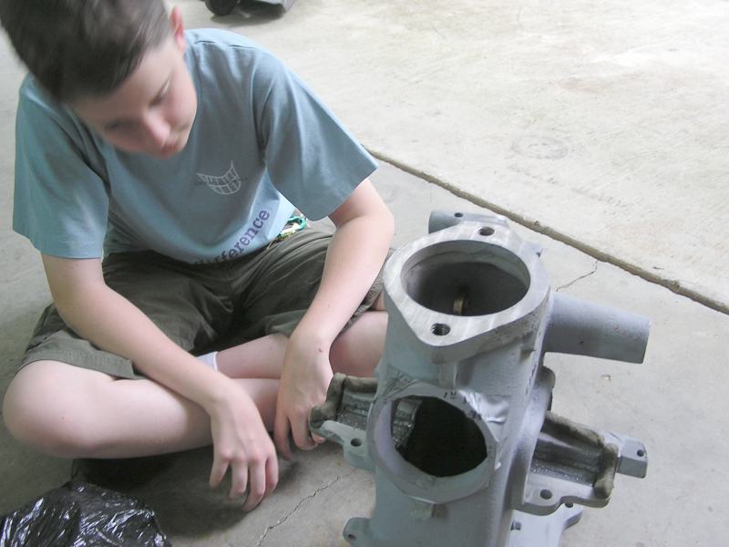
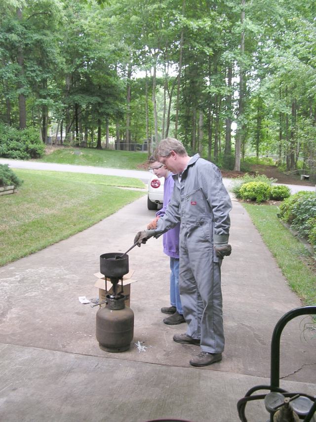
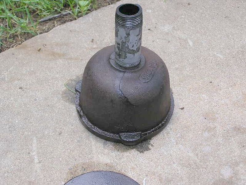 Once home we began the disassembly process to find out what needed to be
repaired and rebuilt to return the engine to its' original glory. Here it looks
like someone over tightened the muffler at some point in its life. A little
welding and grinding will cure.
Once home we began the disassembly process to find out what needed to be
repaired and rebuilt to return the engine to its' original glory. Here it looks
like someone over tightened the muffler at some point in its life. A little
welding and grinding will cure.
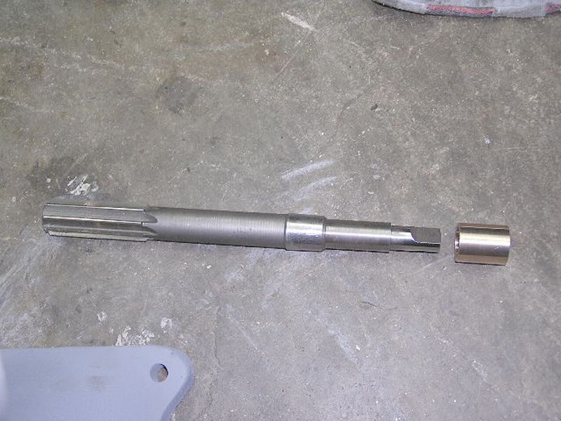
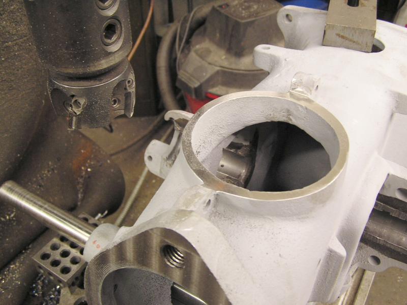
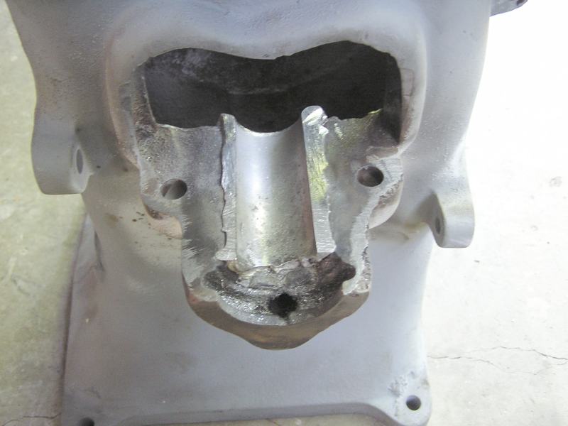
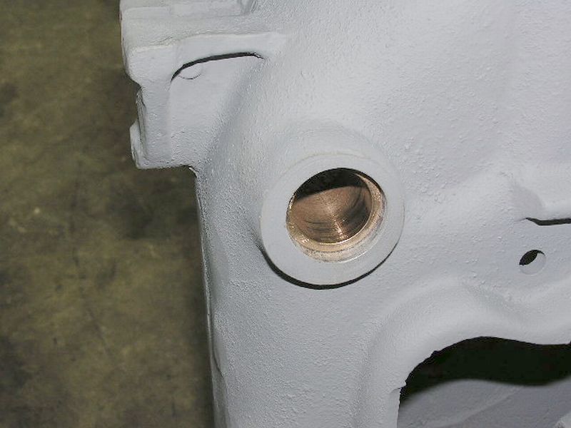 Once the main block was blasted and primed with 2 part urethane primer it was
time to replace the brass bushing supporting the camshaft. The original was a
single long bushing spanning the entire width of the engine with a single 3/8"
oil hole in the top for splash lube to enter. Jim Kirkes and I discussed this at
length and we have concluded to try two separate bushings and to control oil
flow out of the bushings with a small oil seal. You'll see the bushing set back
slightly to make room for the thin oil seal.
Once the main block was blasted and primed with 2 part urethane primer it was
time to replace the brass bushing supporting the camshaft. The original was a
single long bushing spanning the entire width of the engine with a single 3/8"
oil hole in the top for splash lube to enter. Jim Kirkes and I discussed this at
length and we have concluded to try two separate bushings and to control oil
flow out of the bushings with a small oil seal. You'll see the bushing set back
slightly to make room for the thin oil seal.
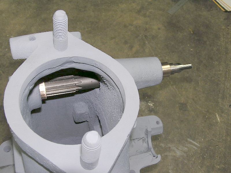
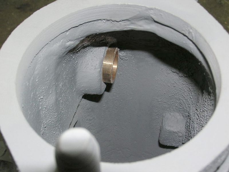 And a view inside the engine showing the shorter bushing. Originally the bushing
spanned all the way across the crankcase. That had to be a bear to machine!
And a view inside the engine showing the shorter bushing. Originally the bushing
spanned all the way across the crankcase. That had to be a bear to machine!
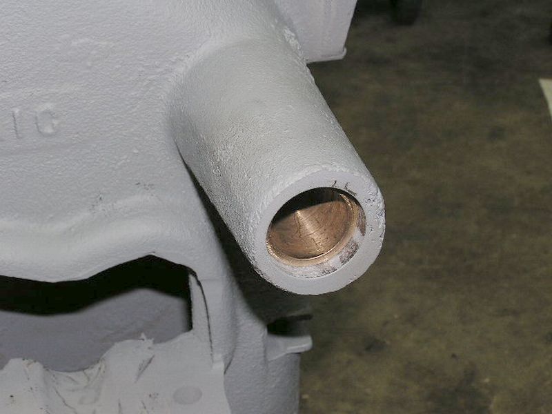 The same on the opposite side, also recessed for the oil seal.
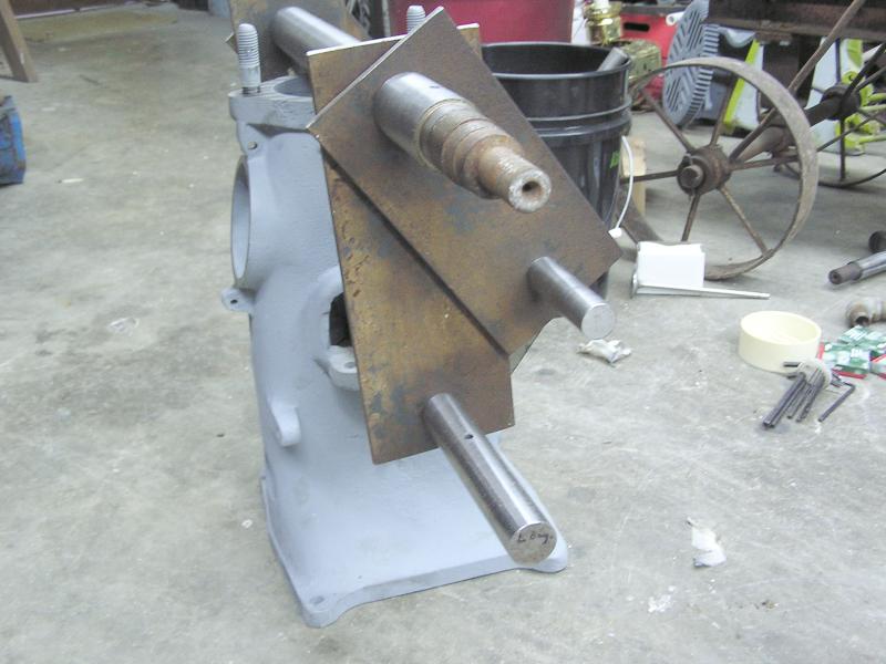
 As
always even the most carefully made bushings will never be dead in alignment
with each other! We did not have a reamer that would span the entire width of
the engine so we had to make a bushing to hold the drive end of the reamer
concentric with the ID of the camshaft bushing.
As
always even the most carefully made bushings will never be dead in alignment
with each other! We did not have a reamer that would span the entire width of
the engine so we had to make a bushing to hold the drive end of the reamer
concentric with the ID of the camshaft bushing.
 Here Devin has just finished reaming the left side bushing. It will be flipped
around and the opposite side cut next.
Here Devin has just finished reaming the left side bushing. It will be flipped
around and the opposite side cut next.
Due to worn mains we decided to re-pour them. Reading the Baker literature it was learned that the cylinder centerline was designed offset from the crankshaft centerline to reduce side thrust on the power stroke. A little CMM work determined that the offset is .750. I was truly surprised at this large offset! Fixtures were made to hold the dummy "crankshaft" in the correct location to the camshaft, the correct distance off the cylinder mounting base, and the .750 off of cylinder centerline. Once all this was set in place it revealed that the camshaft and the cylinder mounting surface were not exactly parallel.
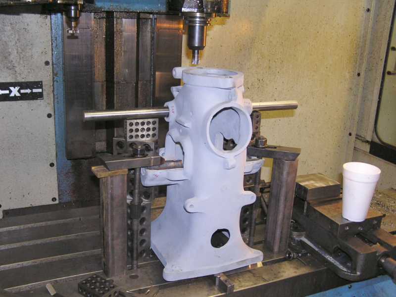 I lugged the block to Tommy's and we set it up in his vertical mill resting the
camshaft on stacks of large parallel blocks. This got it level side to side. A
little jacking on the front and the cylinder mounting surface was flat front to back. One
light
pass with the mill got everything parallel.
I lugged the block to Tommy's and we set it up in his vertical mill resting the
camshaft on stacks of large parallel blocks. This got it level side to side. A
little jacking on the front and the cylinder mounting surface was flat front to back. One
light
pass with the mill got everything parallel.
5/6/05 Update:
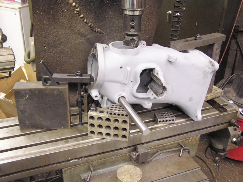 The block was set up in the Bridgeport to mill the crankcase access hole. It was
not close to flat and no amount of gasket would keep it from leaking oil. Here
it is set up at the correct angle on blocks under the camshaft.
The block was set up in the Bridgeport to mill the crankcase access hole. It was
not close to flat and no amount of gasket would keep it from leaking oil. Here
it is set up at the correct angle on blocks under the camshaft.
 The shell milling operation is complete. It took .100 to get it flat again! No
wonder it leaked so much. At the very lower edge of the picture you can see
where the cylinder mounting surface was decked the day before.
The shell milling operation is complete. It took .100 to get it flat again! No
wonder it leaked so much. At the very lower edge of the picture you can see
where the cylinder mounting surface was decked the day before.
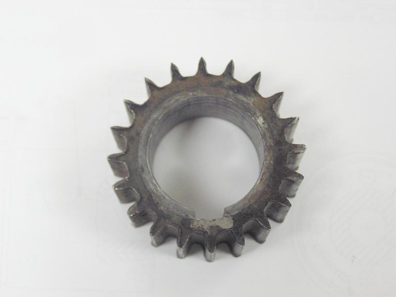 The original timing gear on the crankshaft was removed. Here you can see how bad
the wear is. The teeth are almost knife edged. Luckily the mating camshaft gear
looks new.
The original timing gear on the crankshaft was removed. Here you can see how bad
the wear is. The teeth are almost knife edged. Luckily the mating camshaft gear
looks new.
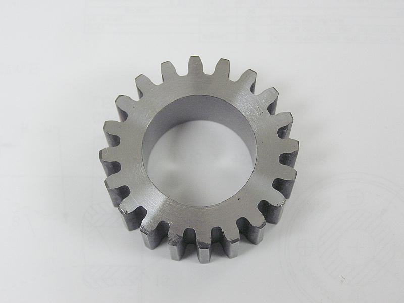 A stock steel gear from Martin was purchased. It was bored for a .001
interference fit and the hub cut off.
A stock steel gear from Martin was purchased. It was bored for a .001
interference fit and the hub cut off.
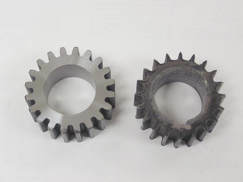 Old and new together. Just need to add the broached keyway....
5/13/05 Update:
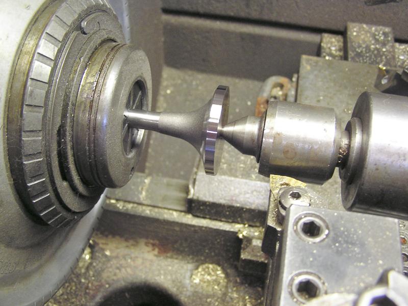 At the fall Portland swap meet and show I picked up a couple of valves for $2
each. They had large heads but had the large shanks that I felt I would need to
fit the oversized exhaust valve cage. For $2 I couldn't buy the stock steel to
make them from scratch! Here the head diameter has been turned down to 1 3/8 Ø.
At the fall Portland swap meet and show I picked up a couple of valves for $2
each. They had large heads but had the large shanks that I felt I would need to
fit the oversized exhaust valve cage. For $2 I couldn't buy the stock steel to
make them from scratch! Here the head diameter has been turned down to 1 3/8 Ø.
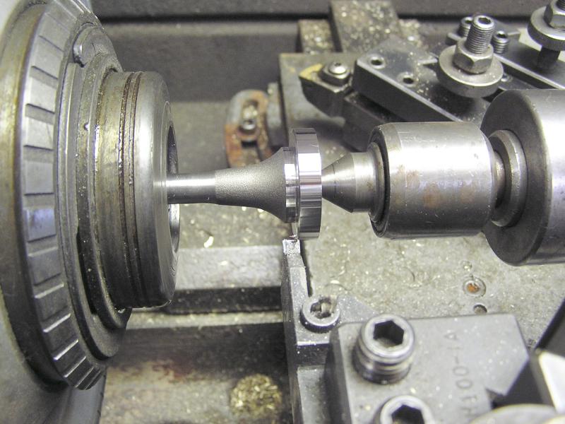 Stepping over to the left and plunging with a cutoff tool sets the head
thickness.
Stepping over to the left and plunging with a cutoff tool sets the head
thickness.
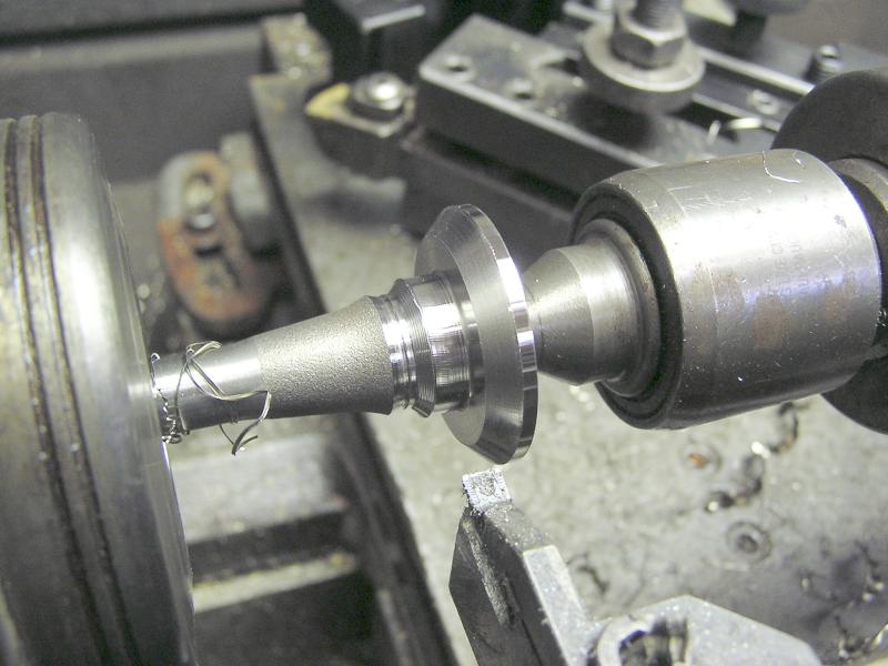 Here the 45° seat angle has been cut.
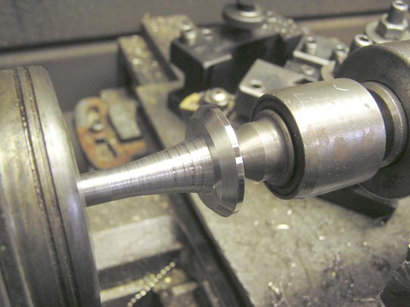 I
didn't have any fancy radius tools so just made a series of steps and then
blended them. It's not a performance engine so the taper ought to be OK.
I
didn't have any fancy radius tools so just made a series of steps and then
blended them. It's not a performance engine so the taper ought to be OK.
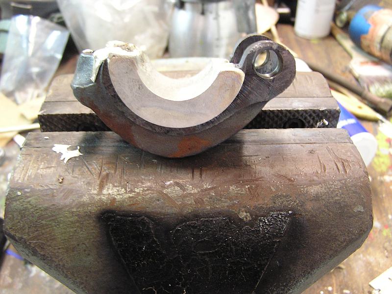
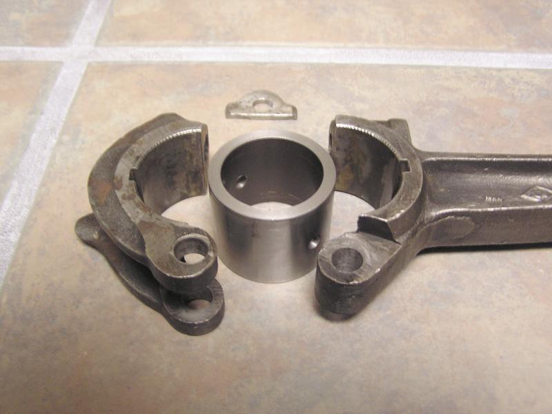 The connecting rod on a Baker Monitor is hinged on one side with a single bolt
on the other. Don't know if the hinge wears out on them all but this one was
awful sloppy. Here I have made a bushing 1.875Ø to assure alignment of the two
halves in preparation for boring the hinge oversized.
The connecting rod on a Baker Monitor is hinged on one side with a single bolt
on the other. Don't know if the hinge wears out on them all but this one was
awful sloppy. Here I have made a bushing 1.875Ø to assure alignment of the two
halves in preparation for boring the hinge oversized.
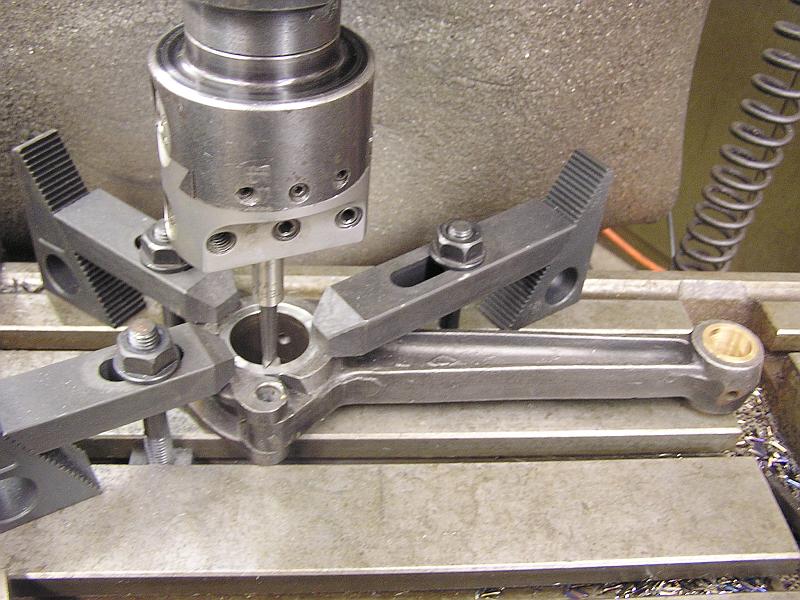 Turns out the simplest method was to just bolt the rod to the Bridgeport table
setting the hinge pin over one of the gaps in the table.
Turns out the simplest method was to just bolt the rod to the Bridgeport table
setting the hinge pin over one of the gaps in the table.
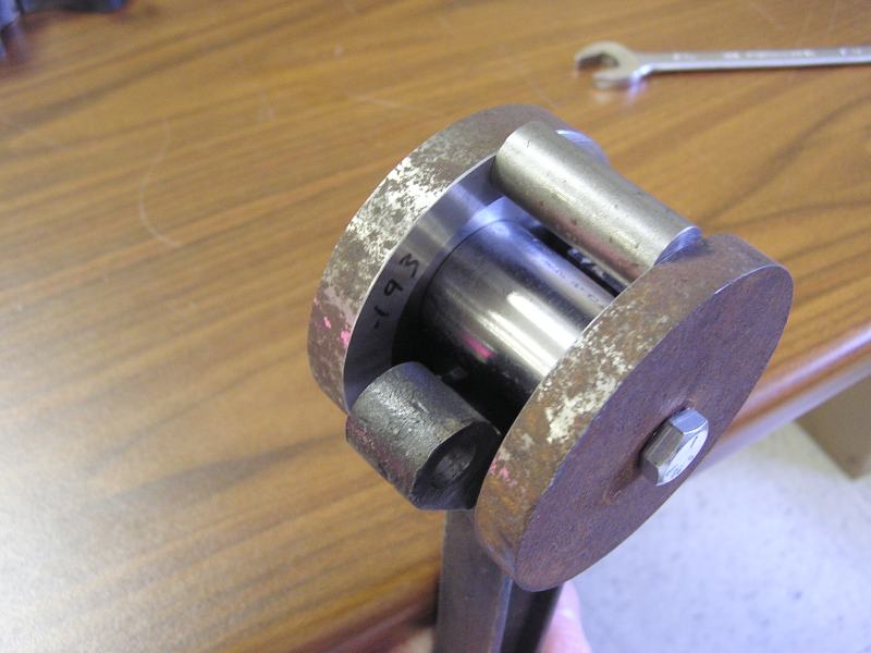
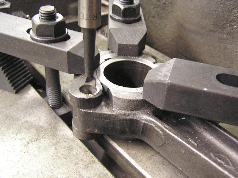 Close up of the boring head tool. The original pin was .375Ø. It took .437Ø to
clean up!
Close up of the boring head tool. The original pin was .375Ø. It took .437Ø to
clean up!
5/16/05 Update:
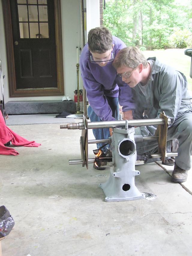
It was a productive weekend. In preparation for pouring new babbitt mains these spacer bars were made to precisely locate the crankshaft the correct distance from the camshaft (5.000") and the correct distance from the cylinder mounting surface. The plates assure the correct .750 offset from the cylinder centerline too. These plates will form a triangle with the camshaft and the cylinder mounting surface, accurately locating the crankshaft.
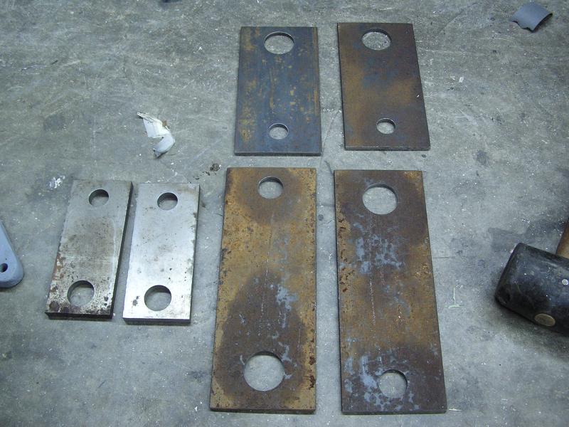 The three pairs of matched plates were made together in pairs to assure they
were exactly the same, center to center. They were bored with a boring head to
give .001 clearance to the TG&P shafts.
The three pairs of matched plates were made together in pairs to assure they
were exactly the same, center to center. They were bored with a boring head to
give .001 clearance to the TG&P shafts.
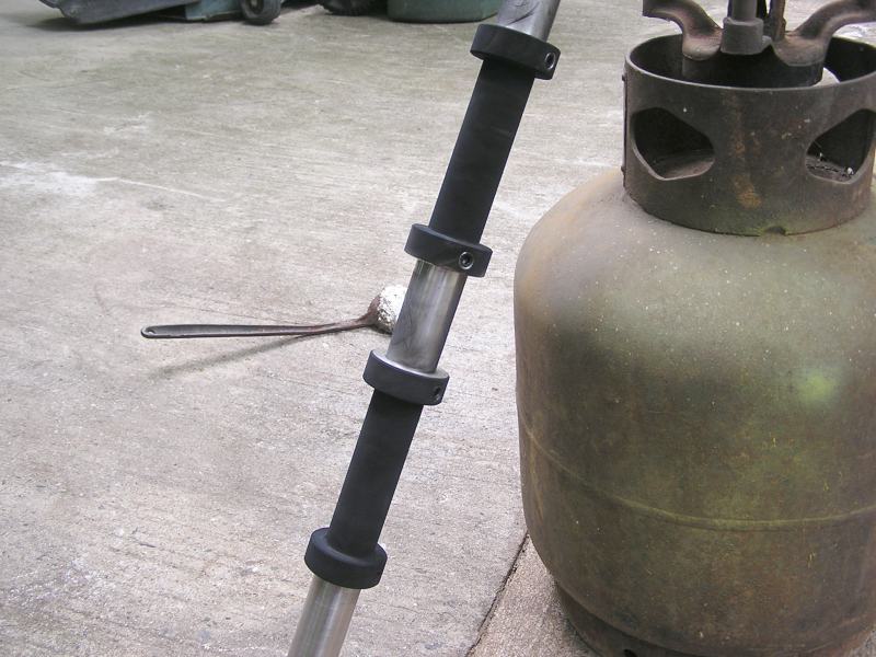
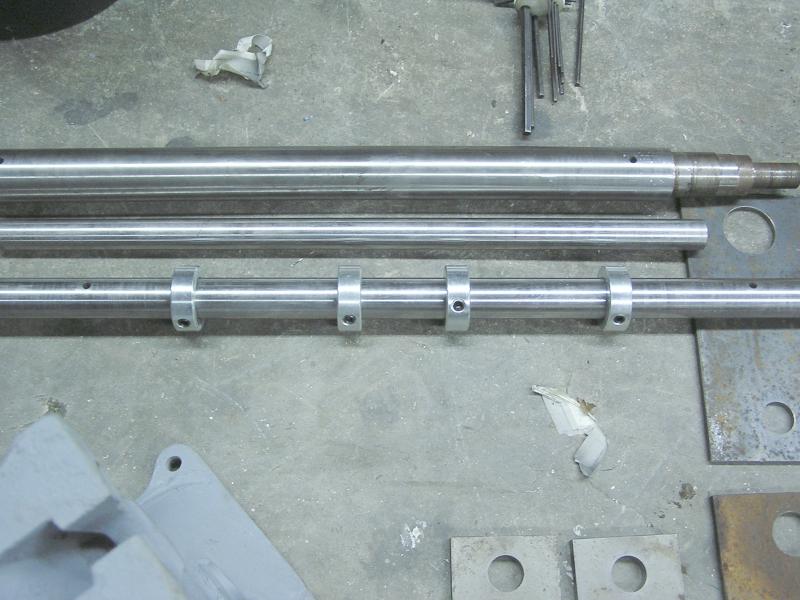 Three pieces of TG&P are to be used. The heavy piece on top will sit on top of
the engine on the cylinder mounting surface. The middle 1" bar will go in the
camshaft bore, and the 1 1/4" bar with the shaft collars is the dummy
crankshaft. The shaft collars control the location of the inner edge of the
babbitt bearing.
Three pieces of TG&P are to be used. The heavy piece on top will sit on top of
the engine on the cylinder mounting surface. The middle 1" bar will go in the
camshaft bore, and the 1 1/4" bar with the shaft collars is the dummy
crankshaft. The shaft collars control the location of the inner edge of the
babbitt bearing.
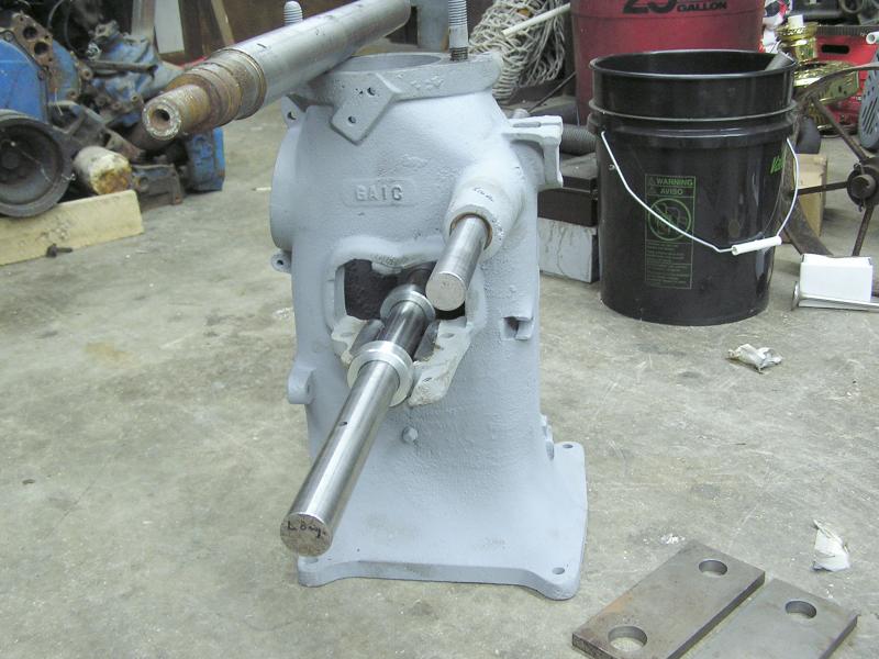 Here the bars have been placed in the engine.
 This plate correctly locates the crankshaft 5.000" from the camshaft to assure
correct mesh of the gears.
This plate correctly locates the crankshaft 5.000" from the camshaft to assure
correct mesh of the gears.
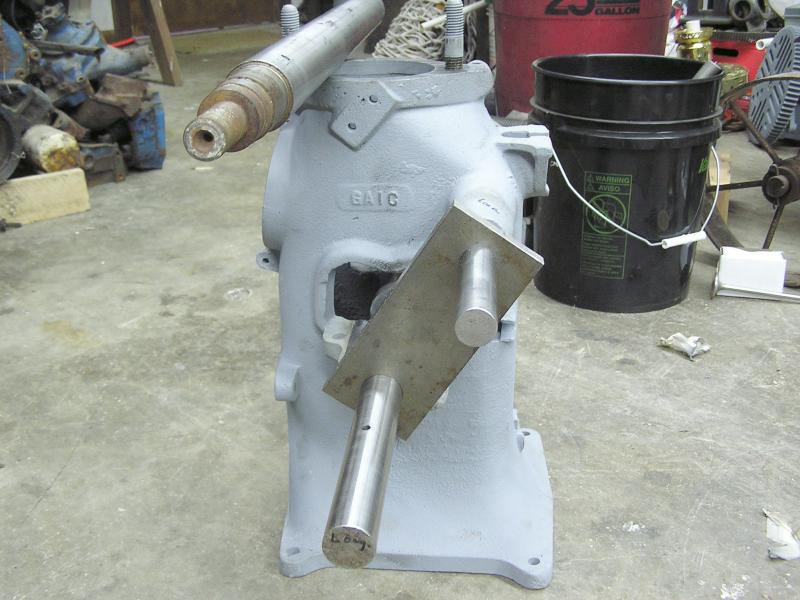
 These
plates locate the crankshaft up and down and also assure the crankshaft is
parallel to the cylinder mounting surface.
These
plates locate the crankshaft up and down and also assure the crankshaft is
parallel to the cylinder mounting surface.
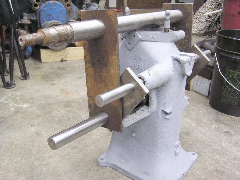
 And
the final set of plates completes the triangle, making everything rigid and
parallel.
And
the final set of plates completes the triangle, making everything rigid and
parallel.
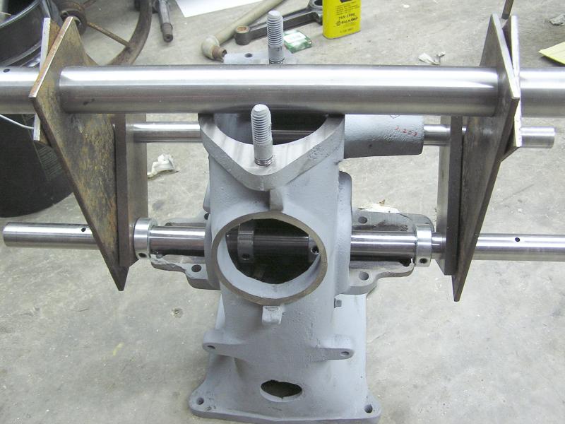 A view from the side of the bars and plates.
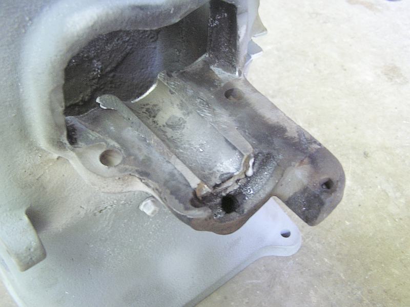
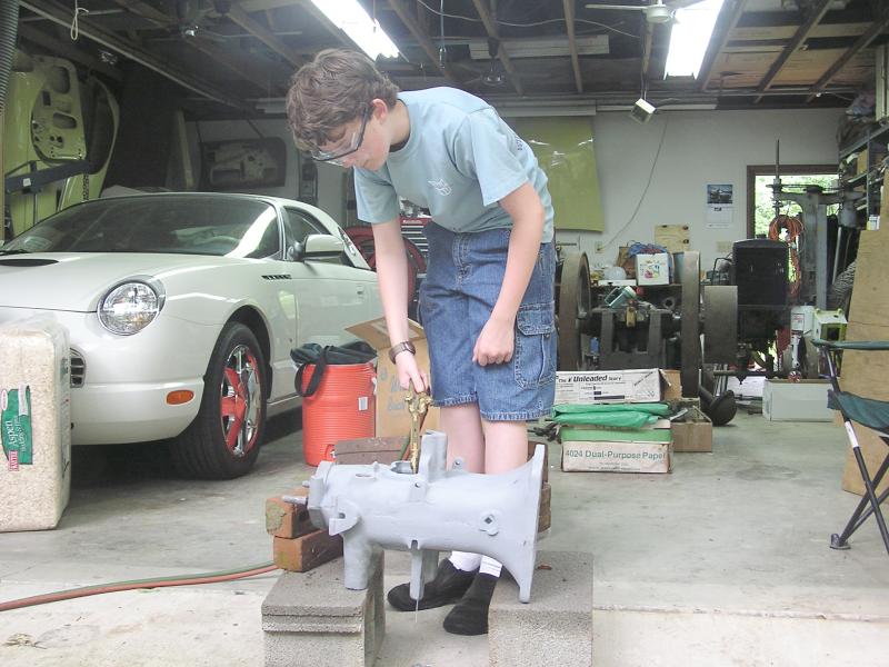 Here Devin is melting the old babbitt out of the main bearings.
 All
done. The babbitt is all out and after some cleaning will be ready for new
metal. Was pleased to see the cast keyways that serve as interlocks for the
babbitt.
All
done. The babbitt is all out and after some cleaning will be ready for new
metal. Was pleased to see the cast keyways that serve as interlocks for the
babbitt.
6/06/05 Update:
 With the old babbitt melted out, the bearing saddles were blasted and tinning
flux brushed on. Devin is playing with the Babbittrite 'cause it is just like
modeling clay.
With the old babbitt melted out, the bearing saddles were blasted and tinning
flux brushed on. Devin is playing with the Babbittrite 'cause it is just like
modeling clay.
 Devin is making the dams with the Babbittrite.
 The dummy crankshaft has been sooted. The shaft collars were positioned and
clamped tight before melting the old babbitt out to set the correct positions.
The two inner collars will form the thrust edges that located the crankshaft
side to side.
The dummy crankshaft has been sooted. The shaft collars were positioned and
clamped tight before melting the old babbitt out to set the correct positions.
The two inner collars will form the thrust edges that located the crankshaft
side to side.
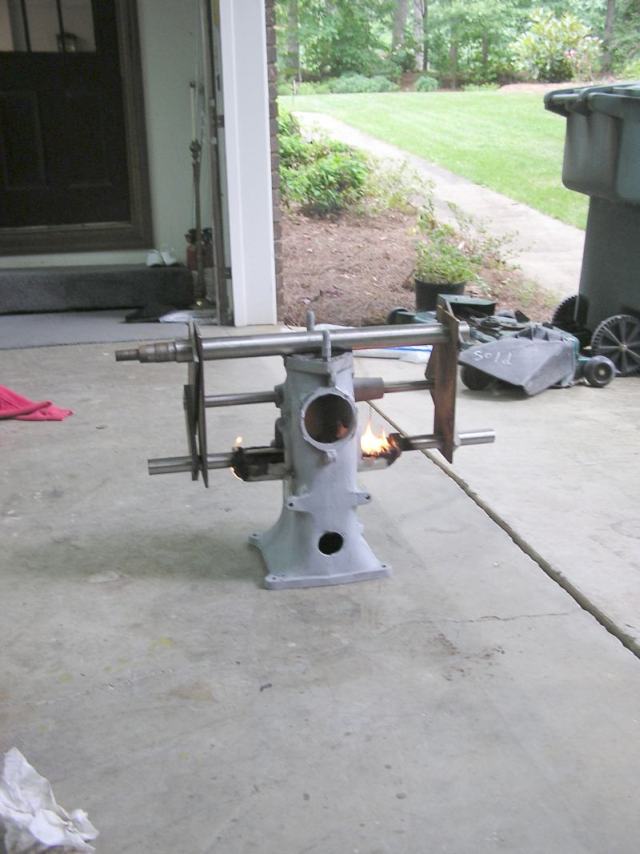 With the shaft and locating brackets in place, the preheat has begun. Things are
pretty hot as the babbittrite has started to burn.
With the shaft and locating brackets in place, the preheat has begun. Things are
pretty hot as the babbittrite has started to burn.
 The pot is hot enough and we are skimming the dross off.
 Here Devin is pouring his first babbitt with a small ladle. He was a little
nervous with the big roaring pot and the molten metal so he wanted my hands on
the ladle too. He did good. I did have him practice good safety too, wearing
full protective clothing and glasses.
Here Devin is pouring his first babbitt with a small ladle. He was a little
nervous with the big roaring pot and the molten metal so he wanted my hands on
the ladle too. He did good. I did have him practice good safety too, wearing
full protective clothing and glasses.
 Here is the finished flywheel side bearing.
 And this is the cam gear side. The little dark spots are staining from the flux
I think. I'm guessing a little Scotchbrite and some solvent will remove.
And this is the cam gear side. The little dark spots are staining from the flux
I think. I'm guessing a little Scotchbrite and some solvent will remove.
6/24/05 Update:
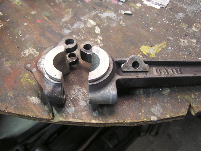
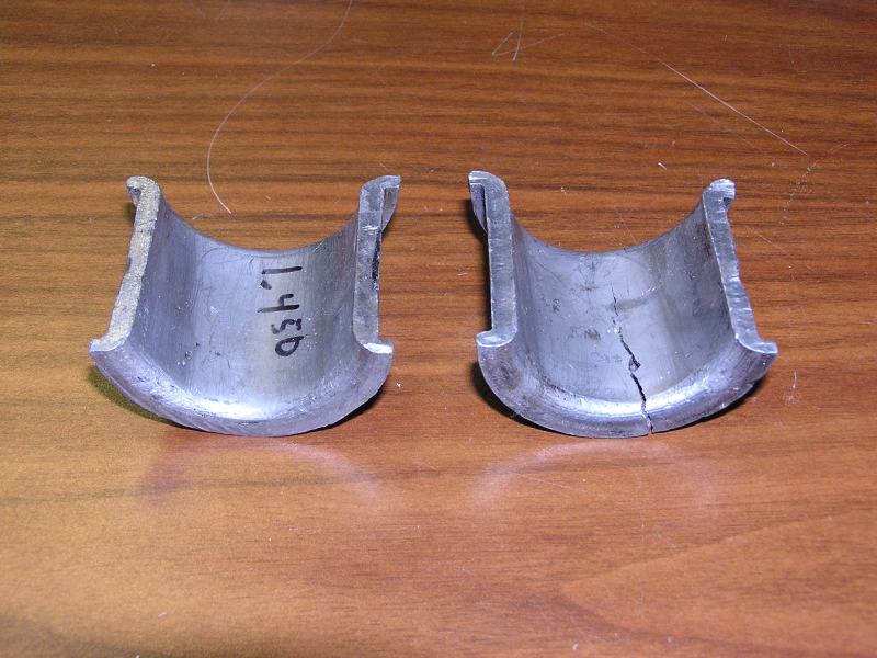 Here are the original babbitt inserts for the connecting rod. The lower one is
cracked and we had to regrind the throw on the crankshaft to get it round
again.
Here are the original babbitt inserts for the connecting rod. The lower one is
cracked and we had to regrind the throw on the crankshaft to get it round
again.
 Since undersize replacement babbitt inserts are not available we decided to cast
our own using this mold. The recess is made with 5° draft to aid removal after
the babbitt is poured.
Since undersize replacement babbitt inserts are not available we decided to cast
our own using this mold. The recess is made with 5° draft to aid removal after
the babbitt is poured.
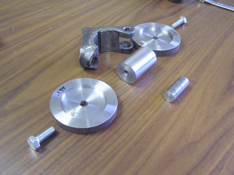
 The dummy shaft is 5/8" smaller than the cap and 5/16" dowel pins were used to
align the dummy shaft to the cap radius. The end plates were installed and the
dowels removed.
The dummy shaft is 5/8" smaller than the cap and 5/16" dowel pins were used to
align the dummy shaft to the cap radius. The end plates were installed and the
dowels removed.
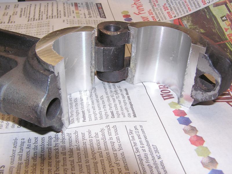
 This is the assembled mold installed over the rod cap. The rod at the top just
keeps the die halves parallel.
This is the assembled mold installed over the rod cap. The rod at the top just
keeps the die halves parallel.
 The rod cap immediately after removal from the mold. Very pleased with how the
thrust surface turned out.
The rod cap immediately after removal from the mold. Very pleased with how the
thrust surface turned out.
 Now it is time to do the connecting rod babbitt using the same mold clamped on.
 The same was done and here are the rod and cap beside each other.
 With a 1/8" shim installed the big end was bored on the Bridgeport. A little
file work to add the radiuses on the sides is all that is left.
With a 1/8" shim installed the big end was bored on the Bridgeport. A little
file work to add the radiuses on the sides is all that is left.
7/21/05 Update:
It's time for a little woodworking. The cart we bought to go under the engine is actually a set of Rock Island axles and wheels that were missing the wooden rails. Richard Fink provided the wood and we are going to convert the rough sawn boards to truck rails.
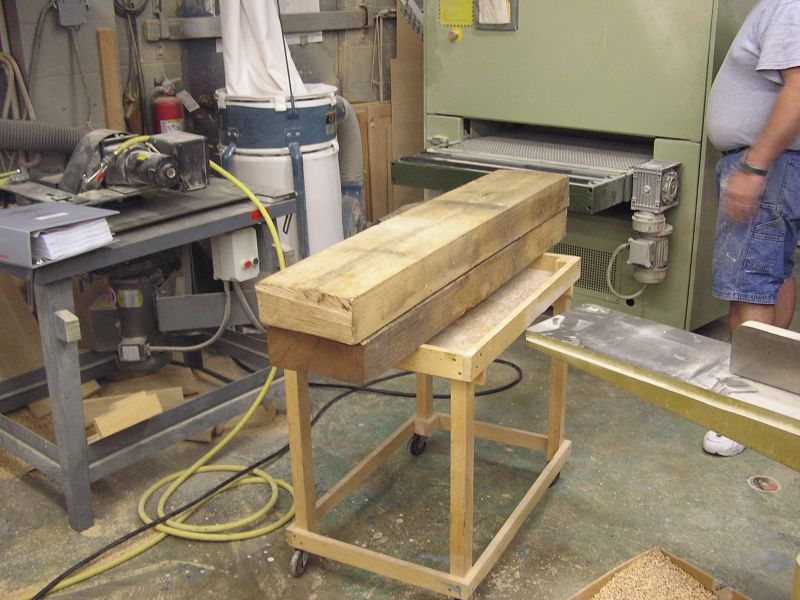 The 8' long, 4" x 10" rough cut oak timbers arrived already cut in half.
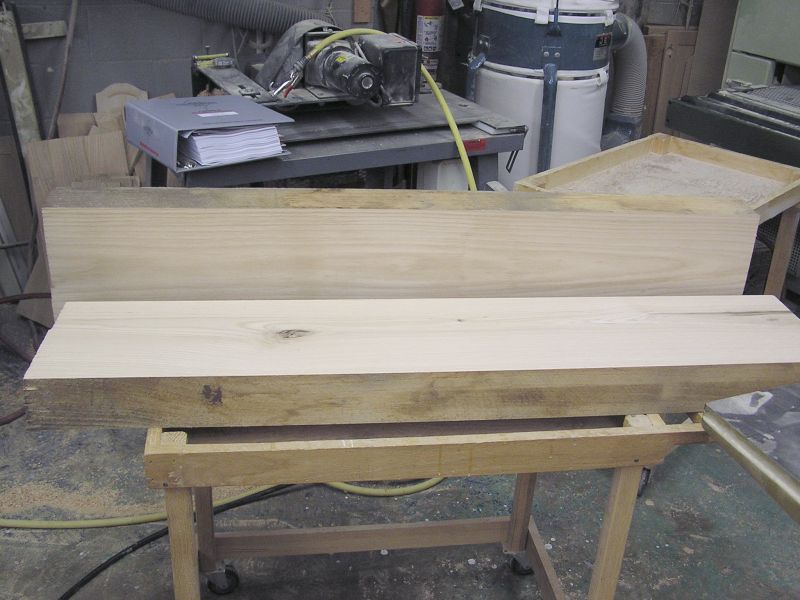 Rather than using the planer we just ran them thru a huge belt sander to get
then to the final 3 1/2" thickness. A very special thank you to Clayton and
David Ballard for their help with this portion of the project. They are in the
high end cabinet building business and certainly have the wood working equipment
to do the job right and quickly.
Rather than using the planer we just ran them thru a huge belt sander to get
then to the final 3 1/2" thickness. A very special thank you to Clayton and
David Ballard for their help with this portion of the project. They are in the
high end cabinet building business and certainly have the wood working equipment
to do the job right and quickly.
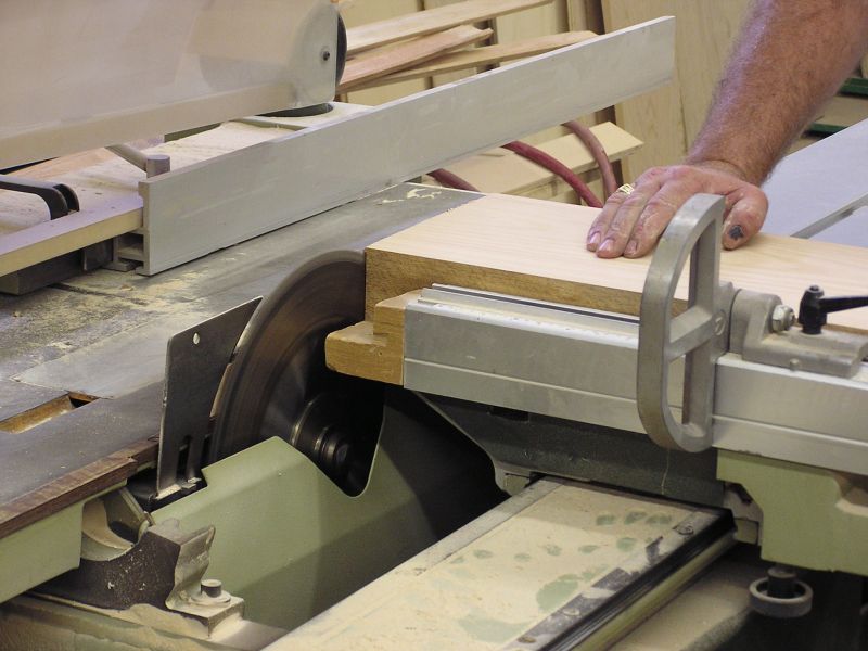 Cutting the end square.
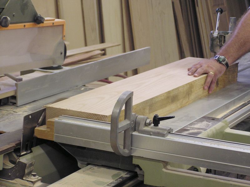 Using a straightline saw (for cutting sheets of plywood) one edge of the 4X10
was trimmed straight. Next the lengths were ripped to leave a 5" wide section.
The drop will be saved for another project someday. Maybe someone on the list
needs some rails for their cart....
Using a straightline saw (for cutting sheets of plywood) one edge of the 4X10
was trimmed straight. Next the lengths were ripped to leave a 5" wide section.
The drop will be saved for another project someday. Maybe someone on the list
needs some rails for their cart....
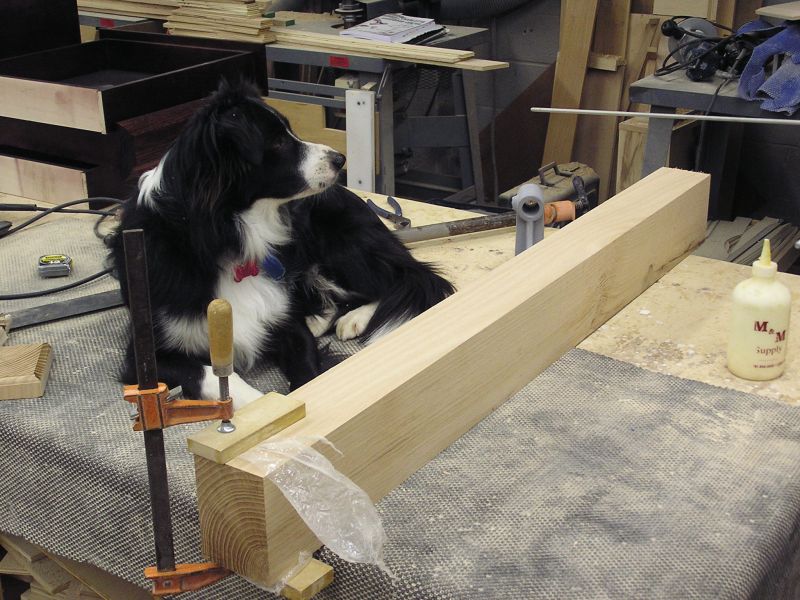 Here is one of the rails after being ripped to the 5" width and sanded smooth on
the remaining 2 sides. There were a couple of cracks that needed to be glued.
Clayton's dog is supervising.
Here is one of the rails after being ripped to the 5" width and sanded smooth on
the remaining 2 sides. There were a couple of cracks that needed to be glued.
Clayton's dog is supervising.
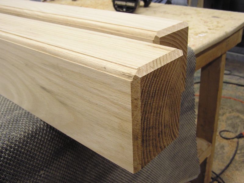 Once the glue dried, David used a router tool to add this fancy edge to the tops
of the rails. Last we put a 1/4", 45° chamfer on the end. I think it makes for a
nice look. I think this is sort of like the edge treatment Dave R. does on his
timbers. I've always admired the wood on his trailers.
Once the glue dried, David used a router tool to add this fancy edge to the tops
of the rails. Last we put a 1/4", 45° chamfer on the end. I think it makes for a
nice look. I think this is sort of like the edge treatment Dave R. does on his
timbers. I've always admired the wood on his trailers.
Devin will be staining and putting polyurethane on these timbers so he can start assembling the cart.
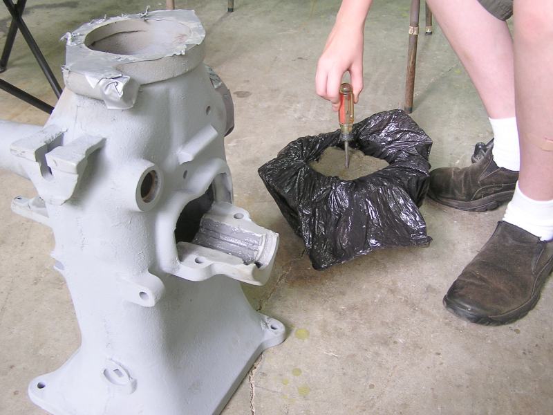
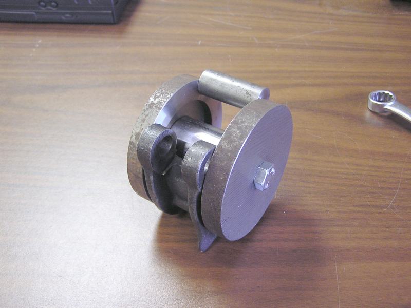
Saturday was spent in the machine shop making a fixture to repair the very worn out intake valve guide. The exhaust valve cage fits into a tapered bore and at the top of this tapered bore sits the intake valve. The project was to build a fixture to allow the intake valve guide to be reamed straight and round again, and in true alignment to the exhaust valve cage.
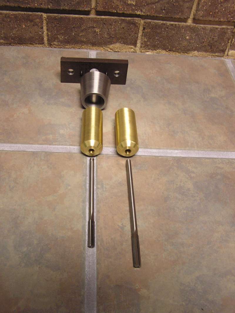 At bottom are the two reamers. The brass piece fits onto the intake valve seat.
The tapered steel part fits over the brass and squares the tool up to the
exhaust valve cage bore. The plate is the clamp plate to hold all firmly in
place. At the bottom of the picture is a .332 and .350 reamer.
At bottom are the two reamers. The brass piece fits onto the intake valve seat.
The tapered steel part fits over the brass and squares the tool up to the
exhaust valve cage bore. The plate is the clamp plate to hold all firmly in
place. At the bottom of the picture is a .332 and .350 reamer.
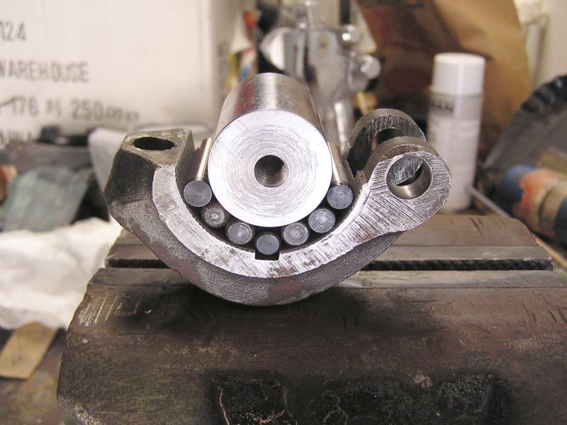
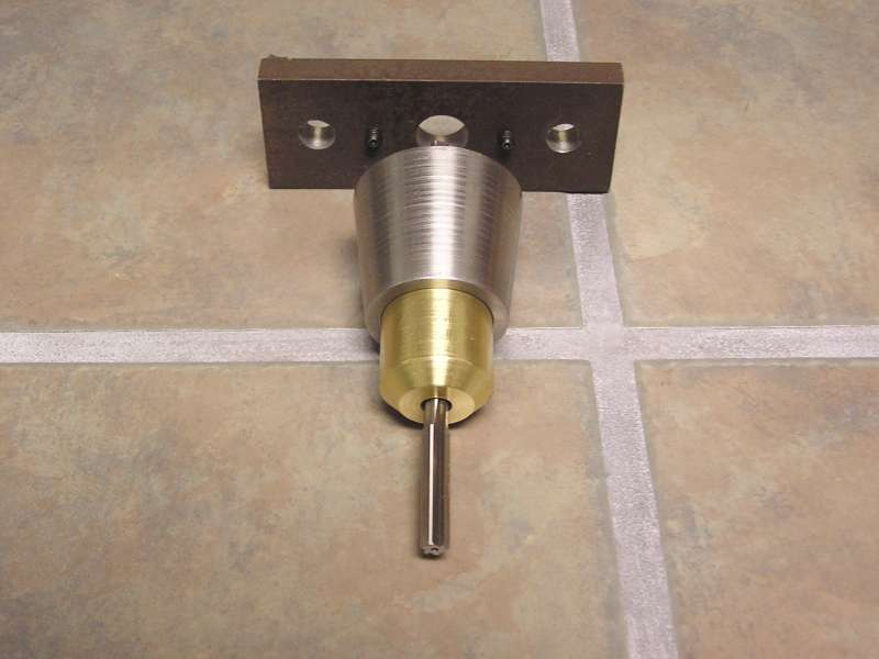 This is the assembly ready to place in the cylinder/head.
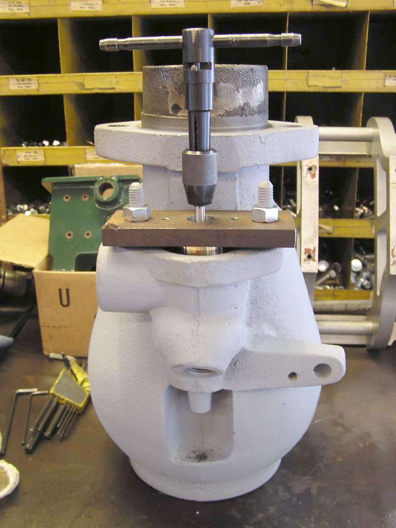 A tap handle is being used to turn the reamer by hand to ream the guide. When it
was all done I had to open it up to .376 to get it completely cleaned up! The
valve was 5/16" Ø originally. That's some pretty significant wear!
A tap handle is being used to turn the reamer by hand to ream the guide. When it
was all done I had to open it up to .376 to get it completely cleaned up! The
valve was 5/16" Ø originally. That's some pretty significant wear!
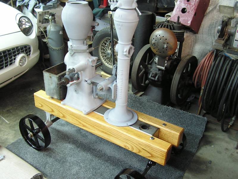 We've loosely assembled the cart and set the engine and pump on it. The
proportions look about right. Between the rails you can just see the stainless
water tank the pump jack will pump from.
We've loosely assembled the cart and set the engine and pump on it. The
proportions look about right. Between the rails you can just see the stainless
water tank the pump jack will pump from.
7/25/05 Update:
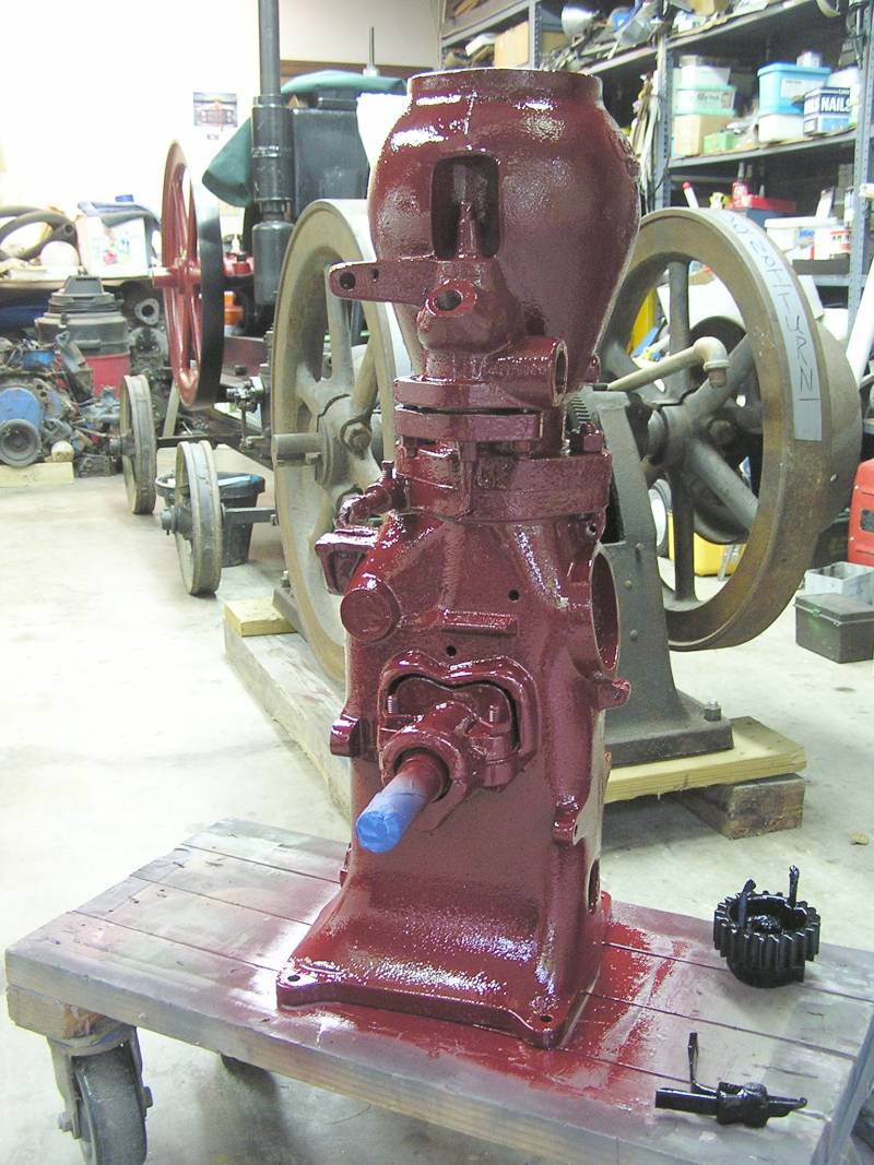 Saturday was spent doing the final lapping on the valves and Sunday morning we
put the cylinder on the engine. A good wipe down with lacquer thinner and then
engine was ready for paint. The original grey is not the most attractive color
on an engine so we opted to paint it this burgundy color.
Saturday was spent doing the final lapping on the valves and Sunday morning we
put the cylinder on the engine. A good wipe down with lacquer thinner and then
engine was ready for paint. The original grey is not the most attractive color
on an engine so we opted to paint it this burgundy color.
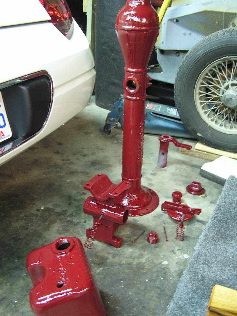 The pumpjack, fuel tank, and several other engine parts were painted in the same
burgundy color.
The pumpjack, fuel tank, and several other engine parts were painted in the same
burgundy color.
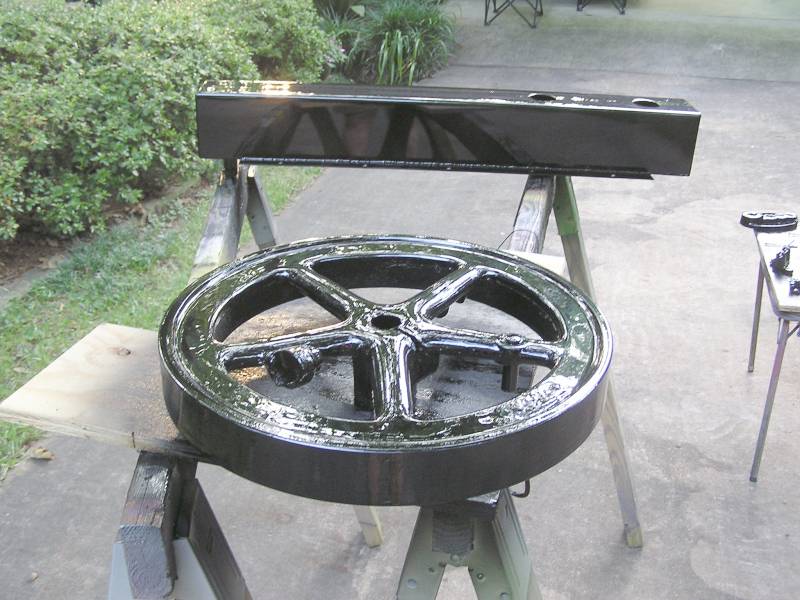 We decided to paint all moving or rotating part in a contrasting color. Black
should go well. The flywheel was the only part we slicked. It was a very rough
casting so it just about had to be done. Behind the flywheel is the small water
tank that will sit between the frame rails. The pump jack will draw water out of
this.
We decided to paint all moving or rotating part in a contrasting color. Black
should go well. The flywheel was the only part we slicked. It was a very rough
casting so it just about had to be done. Behind the flywheel is the small water
tank that will sit between the frame rails. The pump jack will draw water out of
this.
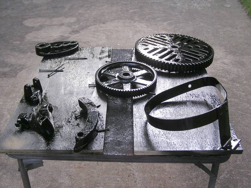 Several miscellaneous engine and pump jack parts have been painted.
8/16/05 Update:
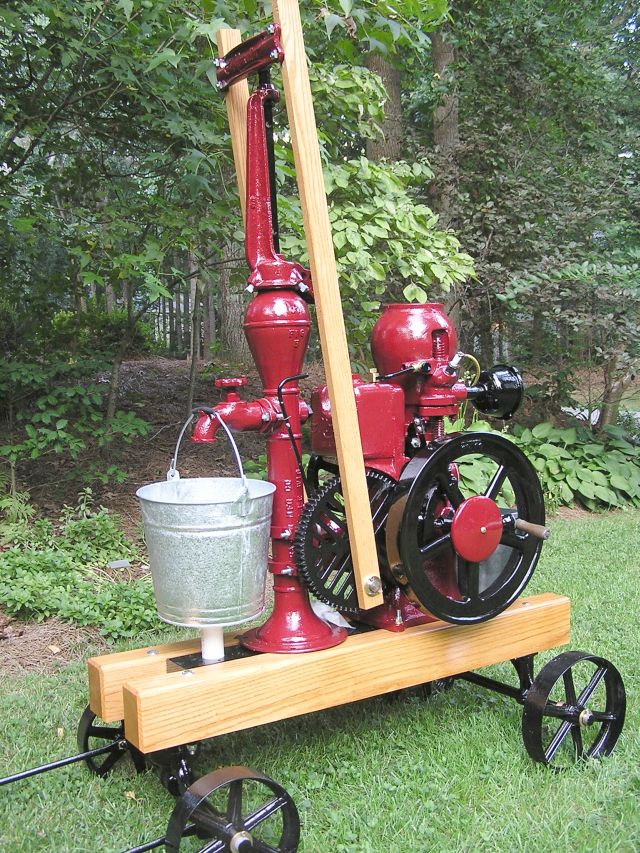 We are finally finished! We've been at it pretty steady since March and it
really feels good to be done with it.
We are finally finished! We've been at it pretty steady since March and it
really feels good to be done with it.
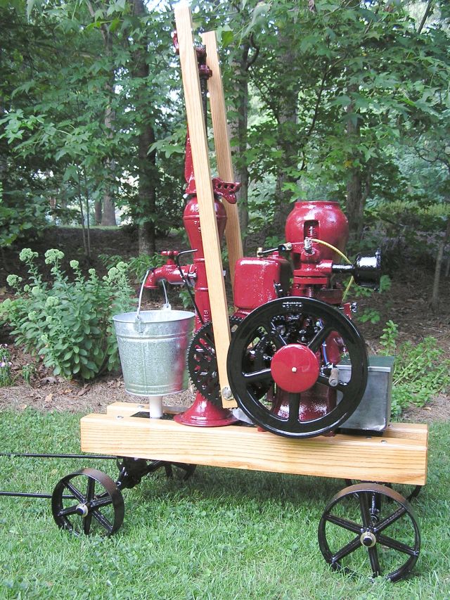 And another picture from a different angle.
THE END!