7/31/15
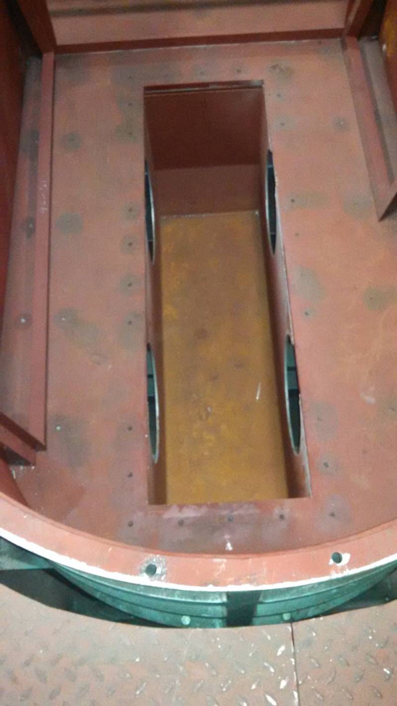
Furnace floor and inductor case are swept very clean in preparation for work.
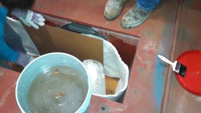
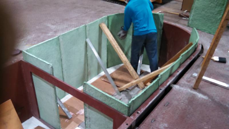
Sodium Silicate solution is brushed and rolled on, one face at a time, and the 1/2" Fibreblanket is rolled into place immediately. Then cardboard sheets are pressed up against the Fibreblanket, along with some braces to hold it in place while the sodium silicate dries.
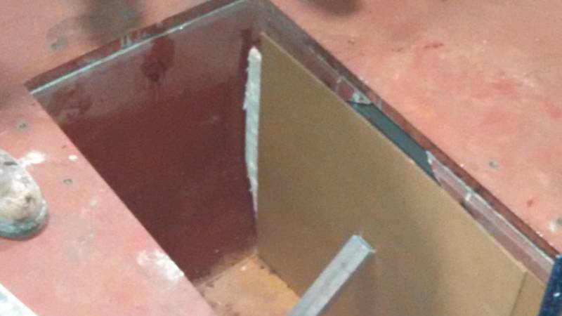
Having full width sheets of Fibreblanket would be handy. The indictor cases measure XX" tall. The blanket supplied is 24" wide, so for now only the lower 24" will be blanketed. The upper 6" will be blanketed later, once silica sand is rammed in the lower part.
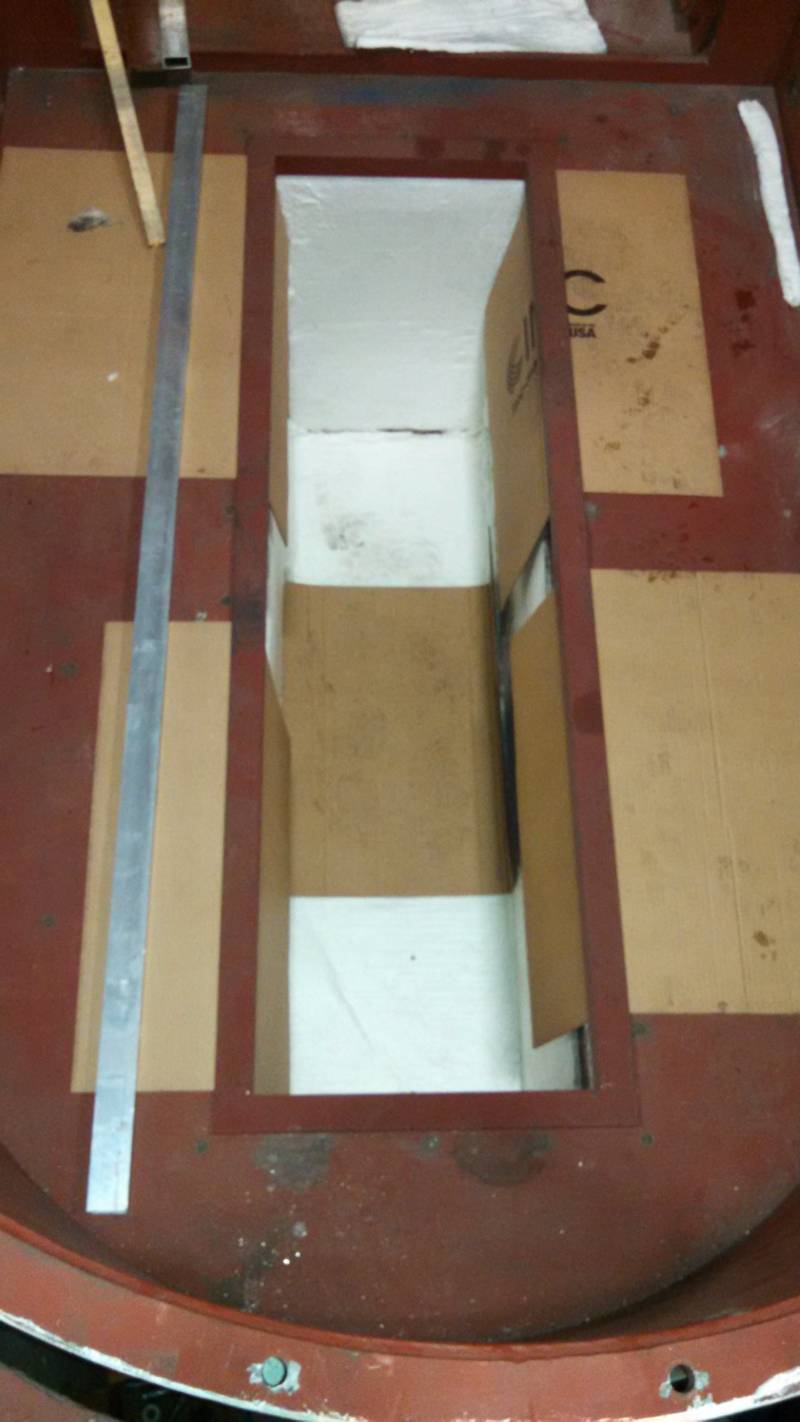
The cardboard and Fibreblanket are held in place at the top by the angle iron frames seen fitted here. Again, full width blanket would be very beneficial.
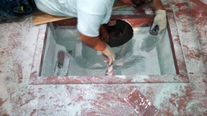
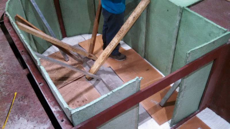
Next the bottom layer of silica sand is placed in the bottom of the inductor cases, taking care not to damage the Fibreblanket. For the large boxes (melt inductors), 8 bags are added. For the small boxes (holding inductors), 4 bags are added. Unrammed, this is about a 5" depth. This is actually deeper than Specialty Foundry likes the bottom layer to be. They aim for 3 to 4" in the first layer.
Once this bottom layer is rammed, a second layer is added that is 1/2 the thickness of the first layer. So this is 4 bags for the melting boxes and 2 bags for the holding boxes. The top of the first layer is raked first with the fork tool to prevent finning of the copper thru the layers.
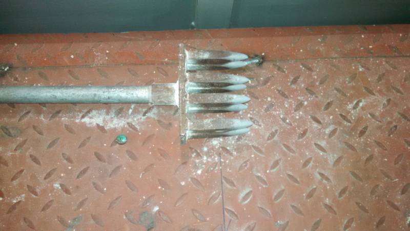
The fork tool is used to de-air the refractory.
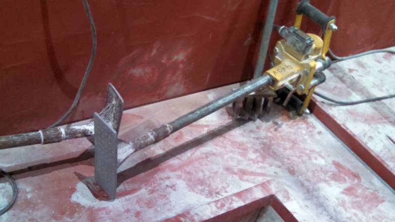
The packing tool that settles the refractory tightly.
This shows the raking step between each layer of silica installed. As each layer is rammed, the vibration tends to cause stratification of the particle sizes, with the largest sized particles floating to the top. By raking, the next layer's smaller particles will settle into the valleys of the raking, reducing the chances of finning.
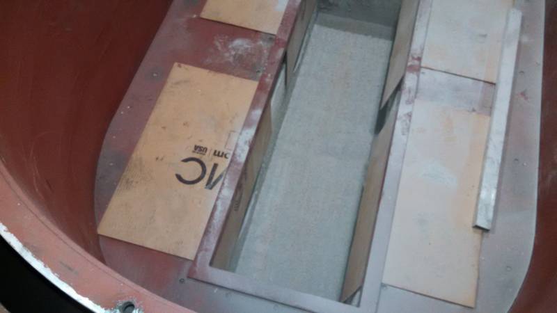
Here the side plates have been installed, which permit the refractory to be built above the level of the holes in the side of the inductor boxes. They just lay in place on the rammed layers below, and additional silica is poured in to hold them in place. Adding refractory w/ raking and ramming continues until packed refractory is 12" from the top of the inductor housing.
9/1/15
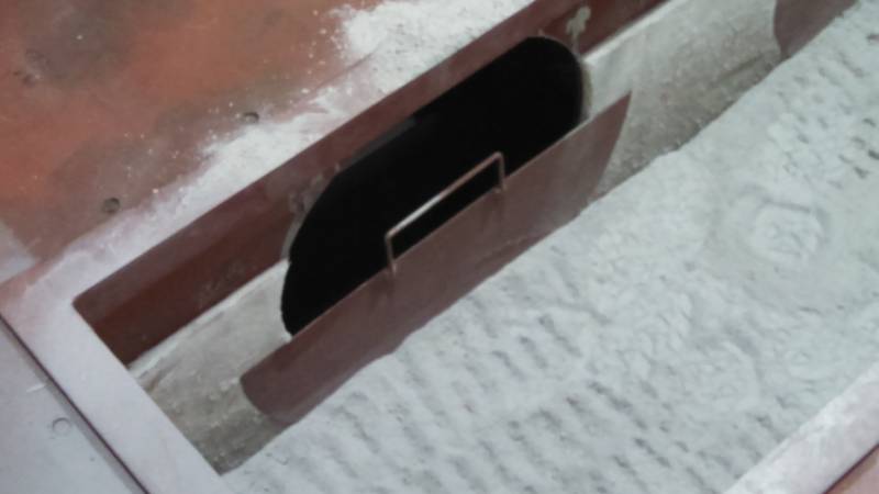
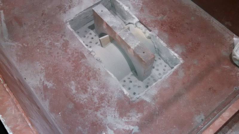
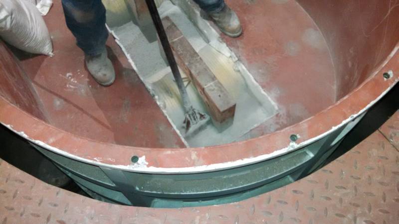
The side plates are eased out and rectangular aluminum bars (2" x 1") about 4 feet in length (or a piece of angle iron) are used to scrape out the refractory, conforming to the lower radius of the opening in the inductor housing.
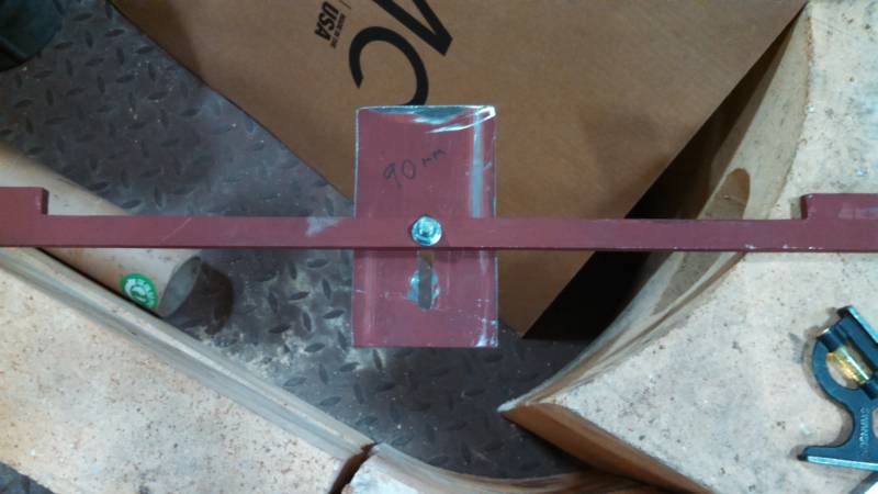
This is the scraping tool fitted with the narrower blade. The blade is set such that 90mm (3.5") of the blade protrudes from the notched side of the bar. The bar is notched to fit the opening width of 20.5" in the inductor case, and serves to keep the scraping tool centered. The 90mm controls the depth of the groove being cut. This is essential to hold the copper loop in the correct position vertically in the next steps.
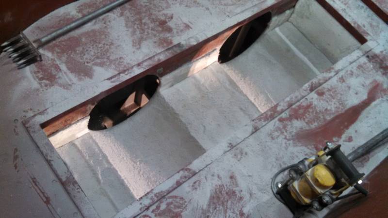
Using the scraping tool, set to the correct depth of 90mm, the tool is dragged thru the refractory to carve out the area where the copper loop will sit. When the loop is installed the ID of the loop and the openings in the inductor case will be concentric. First a narrow blade is used, then a wider blade fitted to make the grove oversize.
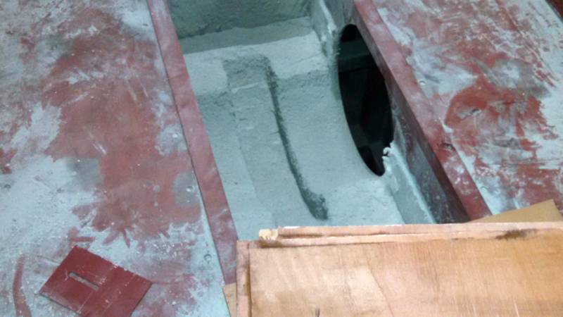
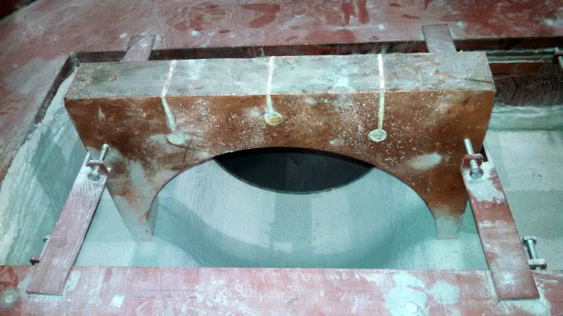
When complete the grooves will look like this. Note they are considerably wider than the copper loop is wide. Refractory will later be rammed back around the loop sides.
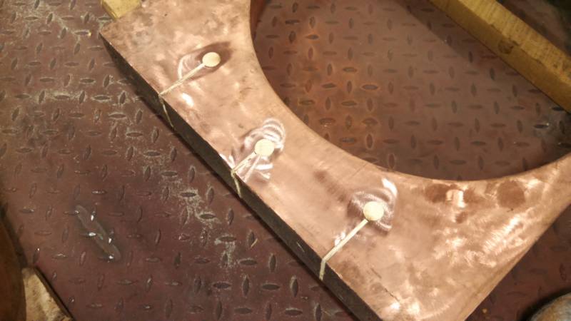
The 6 copper loops have been fitted with 1" poplar dowels and 3/16" oak plywood. These serve as insulators to control current density in the upper part of the loop during the initial warmup.
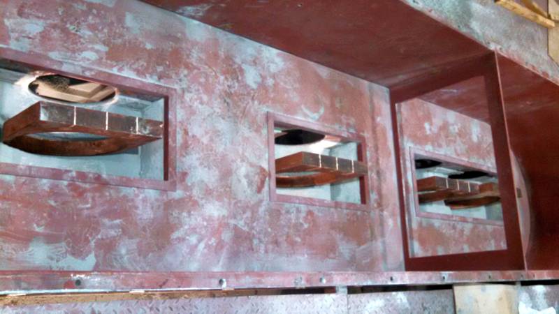
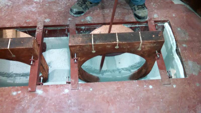
The six copper loops are placed in each groove, awaiting the fixing clamps to be installed. Note the inductor frames around the top of each opening are still in place. These need to be removed prior to installing the fixing clamps in the next step.
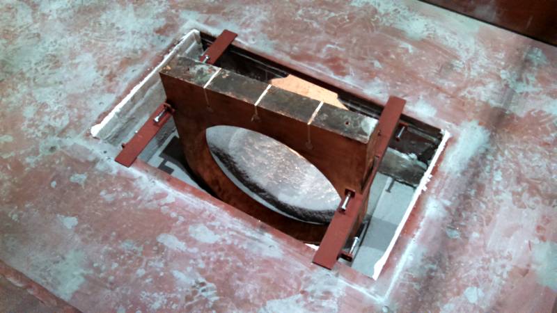
The fixing clamps are attached to each copper loop that will hold the loop at the correct location in the inductor housing. Note: These brackets do not support the weight of the copper loop. The loops are laying on the grooved out refractory underneath each. The bracket only keeps the loops centered and vertical. At this point check to make certain the ID of the copper loop is concentric with the inductor case openings. Should be within an 1/8". Note: 10mm concentricity is the number Huang supplied, but we try and be within 1/8".
Both melting loops have been set in the refractory grooves. They are concentric with the openings in the inductor housing within 1/8". They are also centered in the narrow width of the opening. 205mm from side of copper loops to edges of rectangular opening. Check in 4 locations. Laying a level across the top of the copper loops, shows the top of the loop is 130-135mm above the floor of the furnace.
The side plates, covering the lower half of the inductor housing openings, have been reinstalled so ramming of refractory around the loops can begin. You can see the long, pointed ramming tool being worked around the groove, next to the copper loop. This upsets the refractory, forcing it to move under the loop and pack tightly against the underside and sides of the loop.
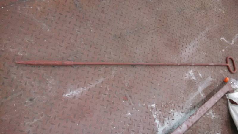
This is the long, pointed tool referenced above.
The layers of silica keep going in with poking and ramming occurring until we are up to the 1/2 way mark.
9/2/15
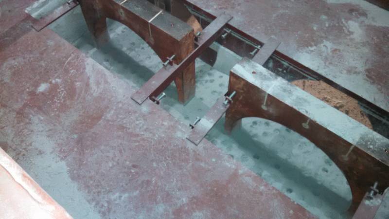
Once the 1/2 way point is reached, the side plates are removed again and a piece of angle iron used to scallop out the refractory even with the lower radius of the inductor box openings.
Next the water cooled bushings are place in the area scalloped out. Note: A couple of days earlier, each bushing was wrapped in a single layer of flat fiberglass tape, 2 to 3" wide x .06 to .1 thick, and heavily coated with motor varnish, and baked in the Michigan oven at a temperature of ____°F for a period of 12 hours.
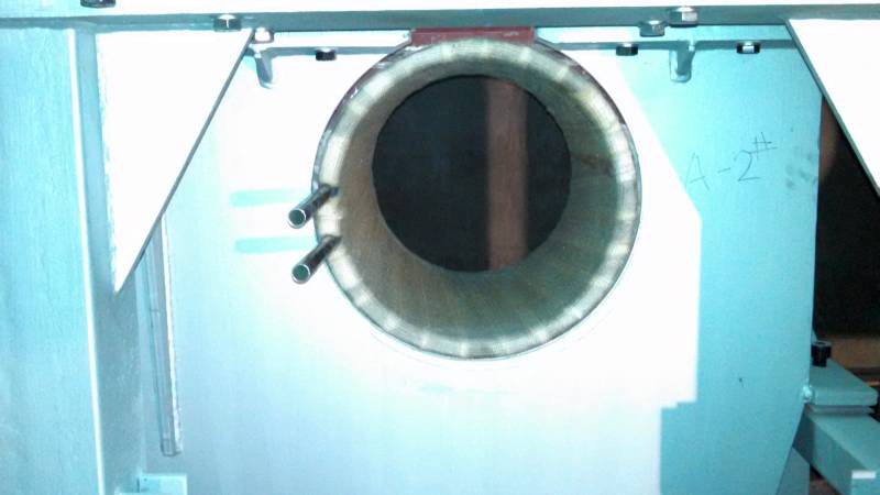
It is SO much easier to place the bushing water connections at a different position than the coil connections. We made this change on Line 6 several years ago. We have placed the bushing water connections at the 9:00 position for all six inductors. Note that because of how the scalloping is done, the bushing is actually laying on both the refractory AND the lower edge of the inductor box. We've never worn thru the bushing's insulation, but I think there is design improvement opportunity here.
9/3/15
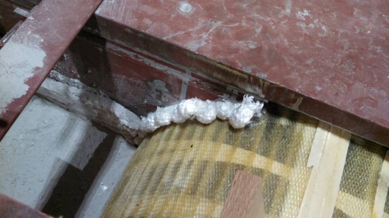
The gap between the top of the bushing and the hole in the inductor case is filled with a variety of ceramic rope products. Along the sides a smaller rope about 1/2" diameter is used. Along the very top a 1" rope is used. Short loops are pushed in place from the outside. They could also be dipped in sodium silicate for additional toughness. We did not use the sodium silicate on this first furnace.
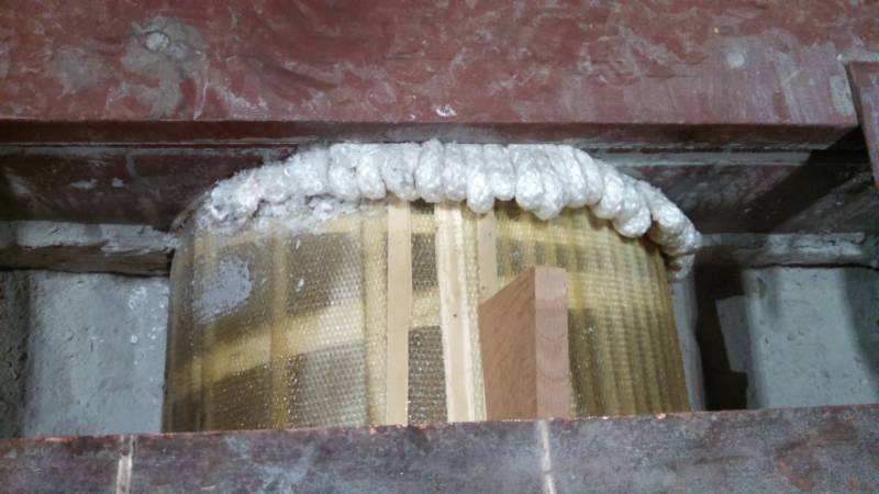
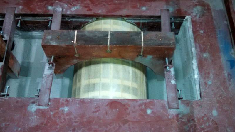
This shows the large rope being used in the upper gap. This is actually pushed in further than desired. An entire day was devoted to pressing in these pieces of rope to fill the gap. There is MUCH room for improvement and productivity gain here! Also note the wooden wedges used to secure the bushing in place while the rope is being stuffed in the gap. One on either side of the loop holds the bushing down. Tap these in gently so as not to lift the copper loop.
9/4/15
Now that the filler rope is in place, the refractory is rammed in the upper half of the inductor housing. Cycles of poking (shown), adding material, and packing with the vibrator takes place until the inductor case is filled even with the furnace floor for now. Also note that the upper 6" of Fibreblanket have been added to the interior wall of the inductor box. As mentioned above, full with Fibreblanket would be useful and save having to piece in.
Packing the silica with the small foot on the vibrator all around the loop and bushing. Note the wooden wedges remain in place for now.
The process of adding, de-airing (forking) and ramming continues until all of the inductor housings are all filled, with only the top of the copper loop sticking out the top.
9/7/15 Labor Day holiday
9/8/15
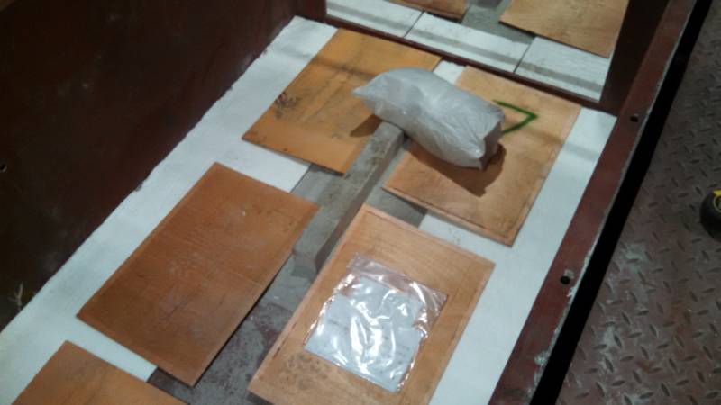
Then the 5/8" or 1/2" soft fiber blanket is added to the bottom of the floor, outboard of the inductor boxes. The pieces of plywood are here just to protect the refractory.
Next the 1" thick hard green boards are stood up around the perimeter of the furnace, and held in place by boards. I'm not certain why Mr. Huang didn't use sodium silicate to hold these fast to the wall. Will ask.
Another view of the same.
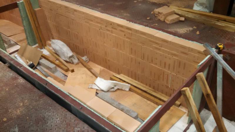
The outside bricks along the straight sections of the center section are complete. Note the bottom three levels of bricks and that there is brick turning inward along the interior partition steel.
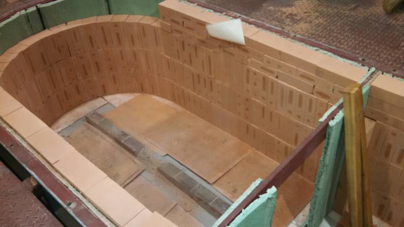
Brick in the south curved end. Note the pattern change in the top three rows of straight section for stability of the wall.
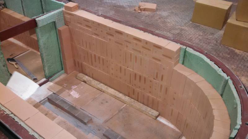
Photo showing the bricks against the interior partition steel.
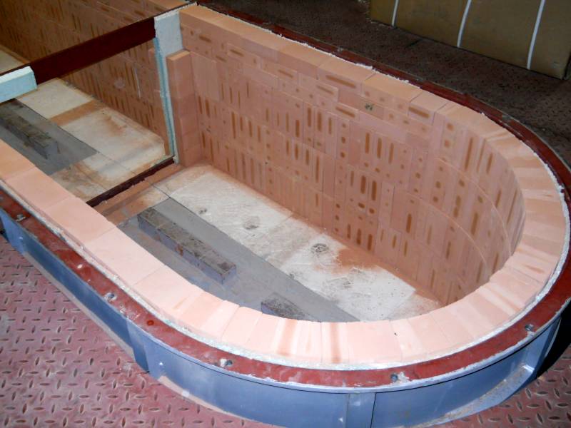
Completed outer row of brick.
Note that the 1/2" fiber blanket is to cover all the steel bottom of the furnace. The openings are the inductor boxes, where there is no steel floor, only refractory. Also note the angle iron frames around each inductor opening are removed. They do not stay in the furnace as part of the build.
9/9/15
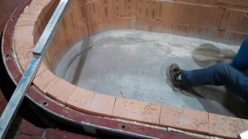
The floor is beginning to go in. Same process of short layers of material, followed with packing, rodding, and more material.
Note the difference in material color. The BOM from China only list "silica sand", but apparently there are two different grades. The grey material is the higher quality material used around the loop/inductors, and the lighter material used in the side walls between the inner and outer bricks. The material we have being tested for qualitative/quantitative analysis is the grey material.
The complete length of the furnace floor has been rammed intentionally high. The combined height of the 3 interior bricks is about 27.5", and the floor should be rammed at 27.75" below the top plane of the furnace. Due to compaction rates you ram high and then dig back down to the -27.75 elevation. Huang wanted us to ram 7" high and then dig back down to the correct elevation. Joe wanted to ram 1" high and only dig back out the 1", which I agree with. We crafted an international treaty and compromised at 4". Still a tremendous amount of work digging all this back out, and since the digging isn't perfect, I believe it will be less compact than if we simply rammed to the correct elevation to begin with. Some research required, but I believe another opportunity for improved efficiency!
9/10/15
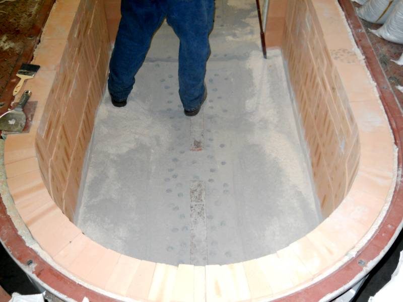
The process of cutting the floor back down to the -27.75 elevation has begun.
Entire floor cut back down.
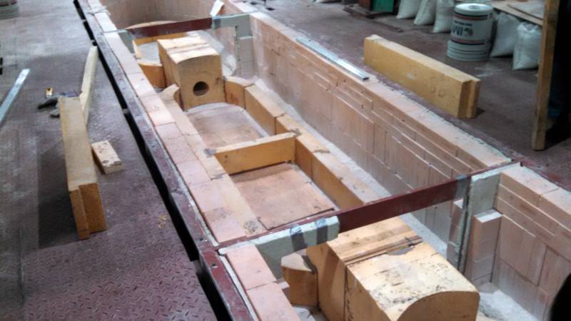
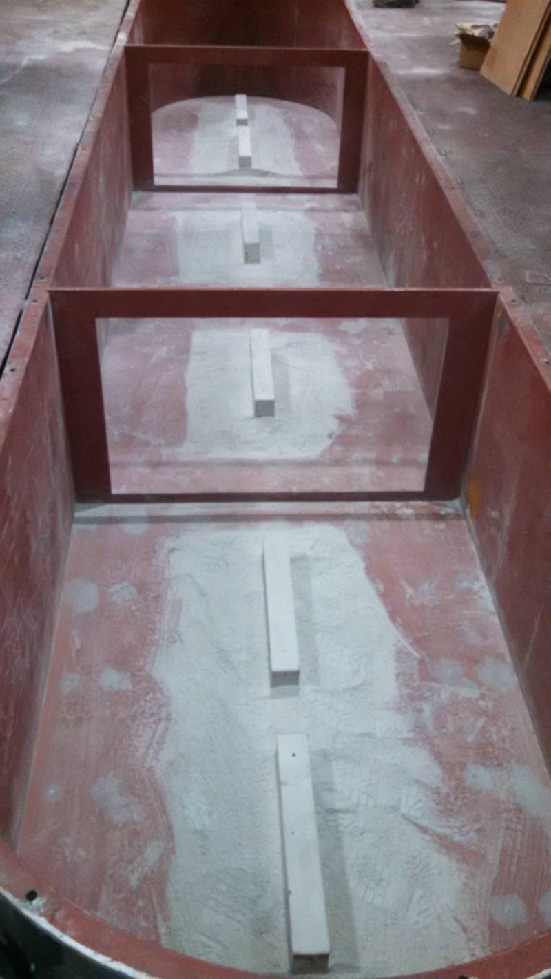
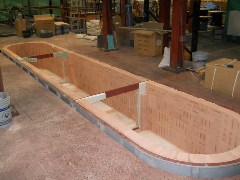
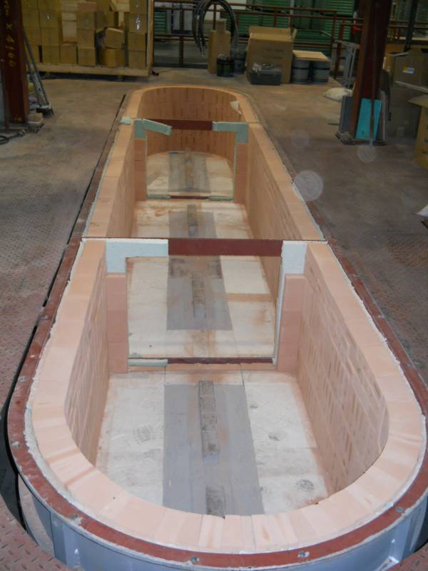
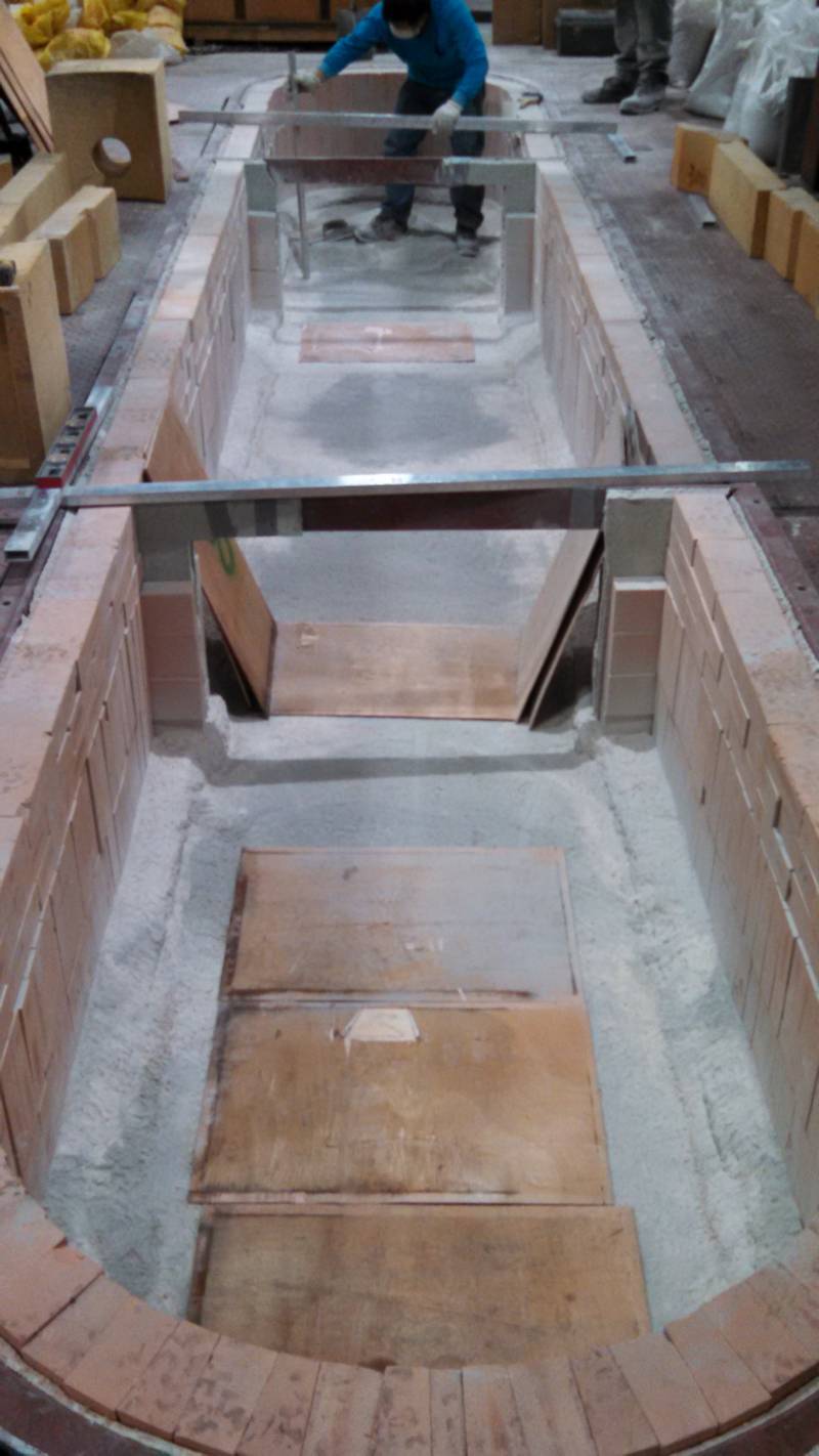
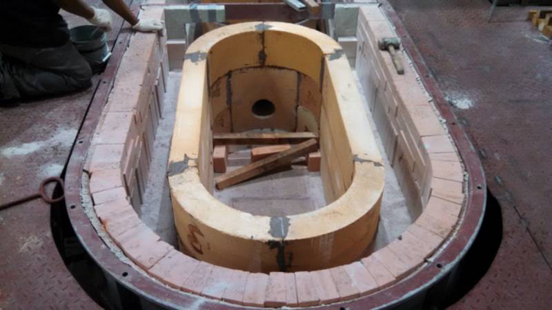
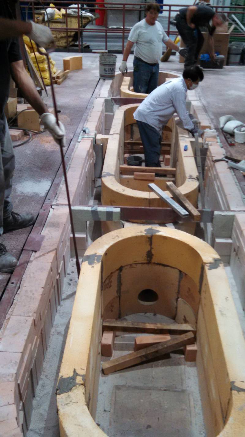
Overview showing the three chambers of the furnace in this first layer of inner bricks.
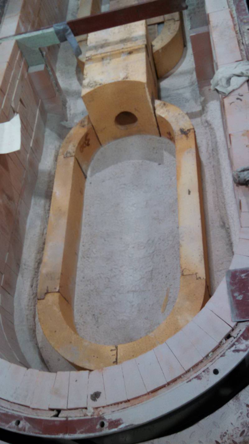
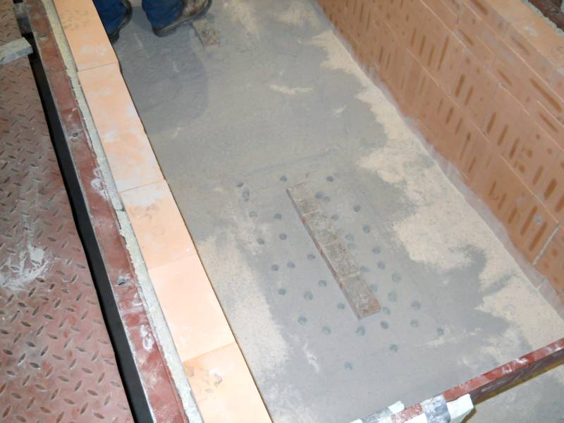
This is one of the two end chambers where the cathode will be melted. The hole in the large brick is where metal moves from the melting zone to the center casting zone.
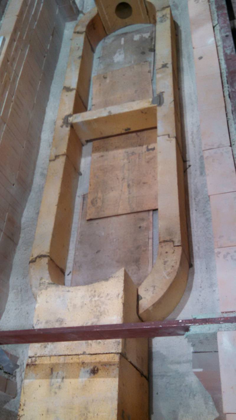
This is the center or casting zone. The boards are there simply to protect the floor over the copper loops.
9/11/15
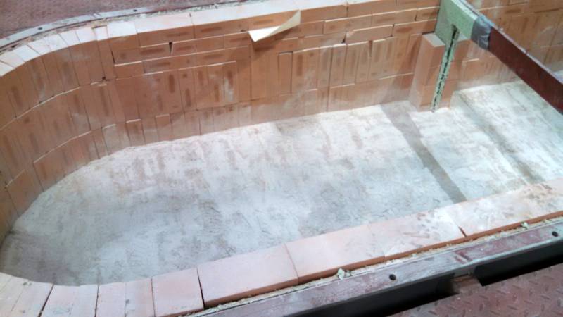
Second and third layers of inner bricks have been placed and now the silica sand is being added in lifts with the normal fork, add material, pack, repeat method used in the lower part of the furnace.
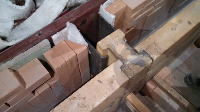
Mr. Huang had us make these steel brackets to hold the H brick in place to make certain the sides of the inner row of bricks cannot move inboard. I think it is doubtful this would happen, given the wide difference in density between the bricks and the copper. I also have concerns if the copper ever gets to these brackets for iron contamination.
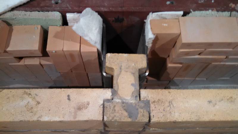
Another view of the brackets and how they bolt to the exterior wall of the furnace.
All layers of brick in place for the entire furnace.